Do you have a question about the Weishaupt WL20/2-C Z and is the answer not in the manual?
Identifies intended users for the manual and required qualifications.
Explains standard symbols used to convey risk and information.
Details warranty exclusions for damage caused by improper use or non-compliance.
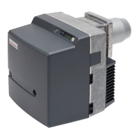
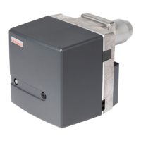
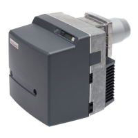
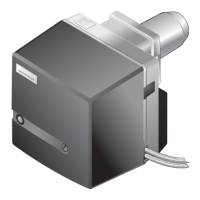
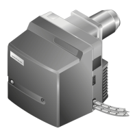
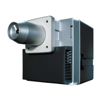
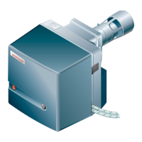
Specifies the intended use of the burner and conditions for its operation.
Outlines critical safety precautions for operation, maintenance, and electrical connections.
Prohibits unauthorized modifications and requires approval for any conversions.
Provides guidelines for the safe and environmentally friendly disposal of materials.
Explains the coding system used to identify the burner model and its specifications.
Indicates the location of the serial number for product identification and service.
Details the operational aspects of air supply, oil supply, electrical components, and program sequence.
Covers approval, electrical, ambient, and fuel specifications.
Details flue gas emission class and sound level measurements.
Specifies combustion heat rating, capacity graph, and data related to installation elevation.
Provides diagrams and measurements for the burner, including options for extensions.
States the approximate weight of the burner unit.
Covers matching burner/heat exchanger, location, and heat exchanger preparation.
Guides on choosing the correct nozzle size based on load distribution and burner capacity.
Details the process of fitting the burner flange, gasket, and ensuring proper sealing.
Details requirements and checks for the oil pump, hoses, and connections according to standards.
Instructs on checking polarity and wiring of connection plugs for electrical setup.
Explains the function of the illuminated push button for status display and error reset.
Describes the meaning of different illuminated push button colors and their operating conditions.
Lists essential conditions and checks required before commencing burner commissioning.
Details how to connect pressure and ammeter devices for mixing pressure and flame signal.
Guides on setting the diffuser and air damper based on required heat output using diagrams.
Outlines the process of starting the burner, setting pump pressure, and checking parameters.
Explains how to determine excess air, flue gas temperature, and calculate flue gas losses.
Emphasizes safety precautions, qualified personnel, and component replacement guidelines.
Lists components, their criteria/lifespan, and recommended service procedures.
Illustrates how to place the burner into specific service positions A and B for maintenance.
Details the procedure for replacing burner nozzles with new ones.
Explains how to check and adjust the distance of ignition electrodes.
Provides step-by-step instructions for removing the burner's mixing head assembly.
Guides on setting the nozzle distance and checking the basic setting of the mixing head.
Details the process of removing the air regulator from the burner assembly.
Explains the procedure for removing and refitting the angle drive, including actuator handling.
Describes how to remove and refit the oil pump, emphasizing correct hose connections.
Details the steps for removing and refitting the fan wheel, ensuring proper alignment.
Provides instructions for removing the burner motor, including related components.
Outlines the procedure for replacing the oil pump filter and gasket.
Guides on how to safely replace the fuse within the combustion manager.
Explains how the combustion manager indicates faults via the illuminated push button.
Lists common faults and operator-correctable causes when the push button is off.
Describes how to read error codes and reset the burner after a fault.
Lists faults, causes, and rectifications requiring qualified personnel.
Provides a table of common operating issues, their causes, and solutions for qualified personnel.
Presents a table for converting units of pressure between different scales.
Displays the electrical wiring diagram for the burner control system.
Provides guidance on oil supply installation, suction resistance, and related components.
Shows an exploded view of major burner components with part numbers.
Lists various spare parts with their descriptions, positions, and order numbers.