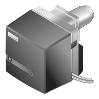
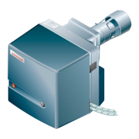
Installation and operating instruction
Oil burner WM-L20/2-A R (W-FM100/200)
4 Installation
83252902 1/2019-09 La
22-84
4.3.2 Set mixing head without combustion head extension
Hinge open the burner [ch.9.3].
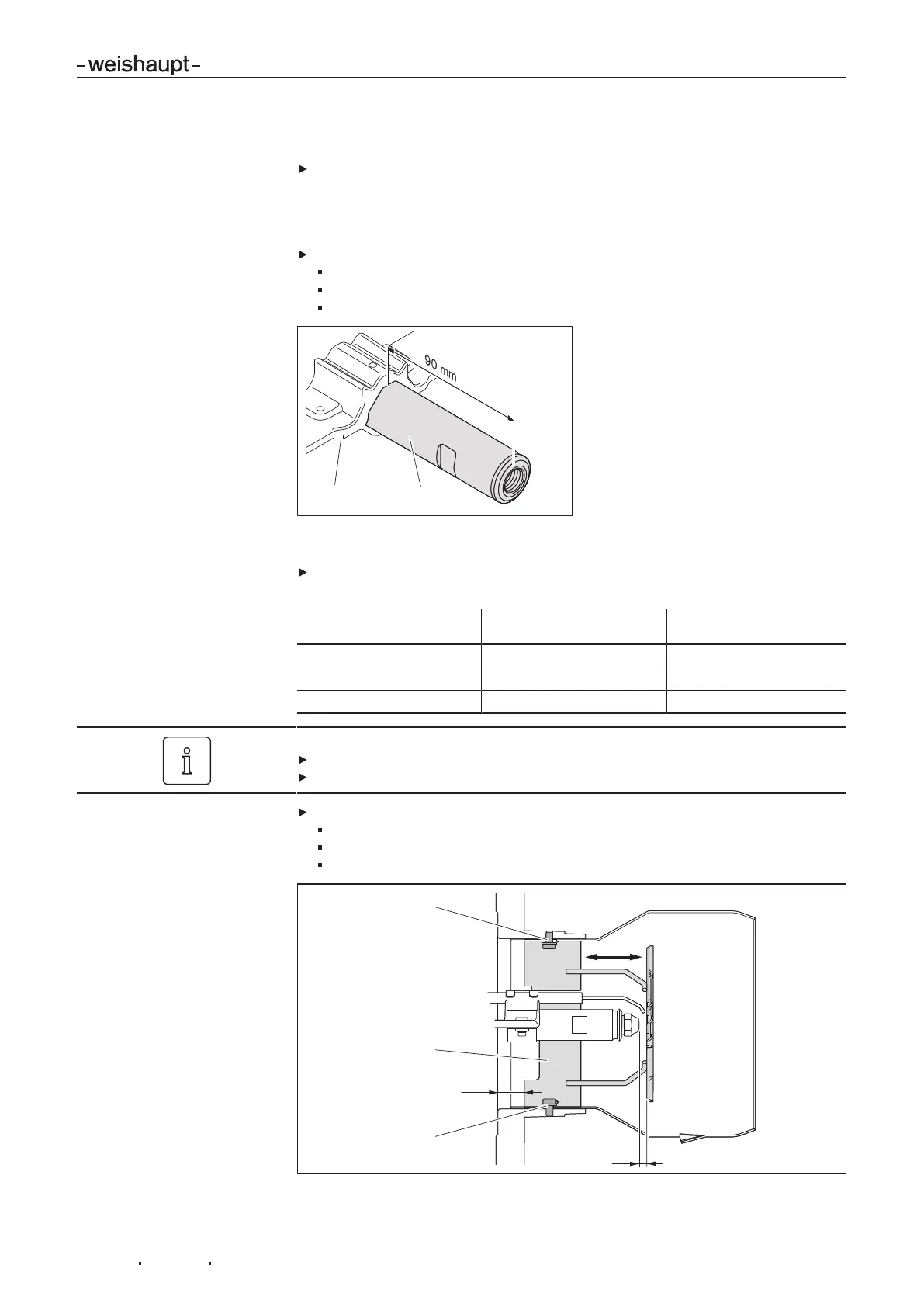
1. Set distance nozzle support to nozzle body
The distance between nozzle support and nozzle body2 must be 90 mm.
If necessary adjust nozzle body:
Undo screws1 on nozzle support.
set distance nozzle support to nozzle body to 90 mm,
Re-tighten screws.
2. Set nozzle distance
Check nozzle distance (dimension A) using auxiliary dimension2 between dif-
fuser sleeve and burner flange.
Nozzle distance (dimen-
sion A)
Auxiliary dimension 2
7 mm 25 mm
10 mm 28 mm Factory setting
13 mm 31 mm
The diffuser could become soiled if incorrectly positioned.
Determine auxiliary dimension 2 at a minimum of 3 points (each offset by 120°).
Check alignment of nozzle assembly to diffuser (even aperture).
If necessary set nozzle distance:
Undo screws1.
Rotate diffuser sleeve3, until auxiliary dimension2 has been reached.
Re-tighten screws.
 Loading...