7
3.2 Basic function
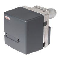
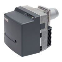
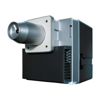
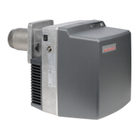
Burner type
• Fully automatic oil atomising burner with fan
• Two stage operation
Digital combustion manager
Main points:
• Safety via internal fuse
• Control and monitoring of all burner functions
• Safety via two microprocessors (reciprocal monitoring)
• Data bus connection (eBUS)
• Signal lamp to show operational status (see also
Ch. 6):
Green Burner operating
Flashing green Burner operating with weak
flame signal
Orange Burner start, internal test
Flashing orange Ignition phase
Red Burner lockout
Flashing orange / red Low voltage or internal safety
fault
Flashing green / red Extraneous light
2 x flashing red / Over-voltage
orange, short pause
Flickering red Optical data transfer
(not used)
Electric servomotor
Setting of the individual operating points is carried out by
the limit and auxiliary switches on the servomotor (Ch. 5.3)
Flame sensor
Monitors the flame signal at each operating phase. If the
flame signal does not concur with the sequence of
operation, a safety shutdown is initiated.
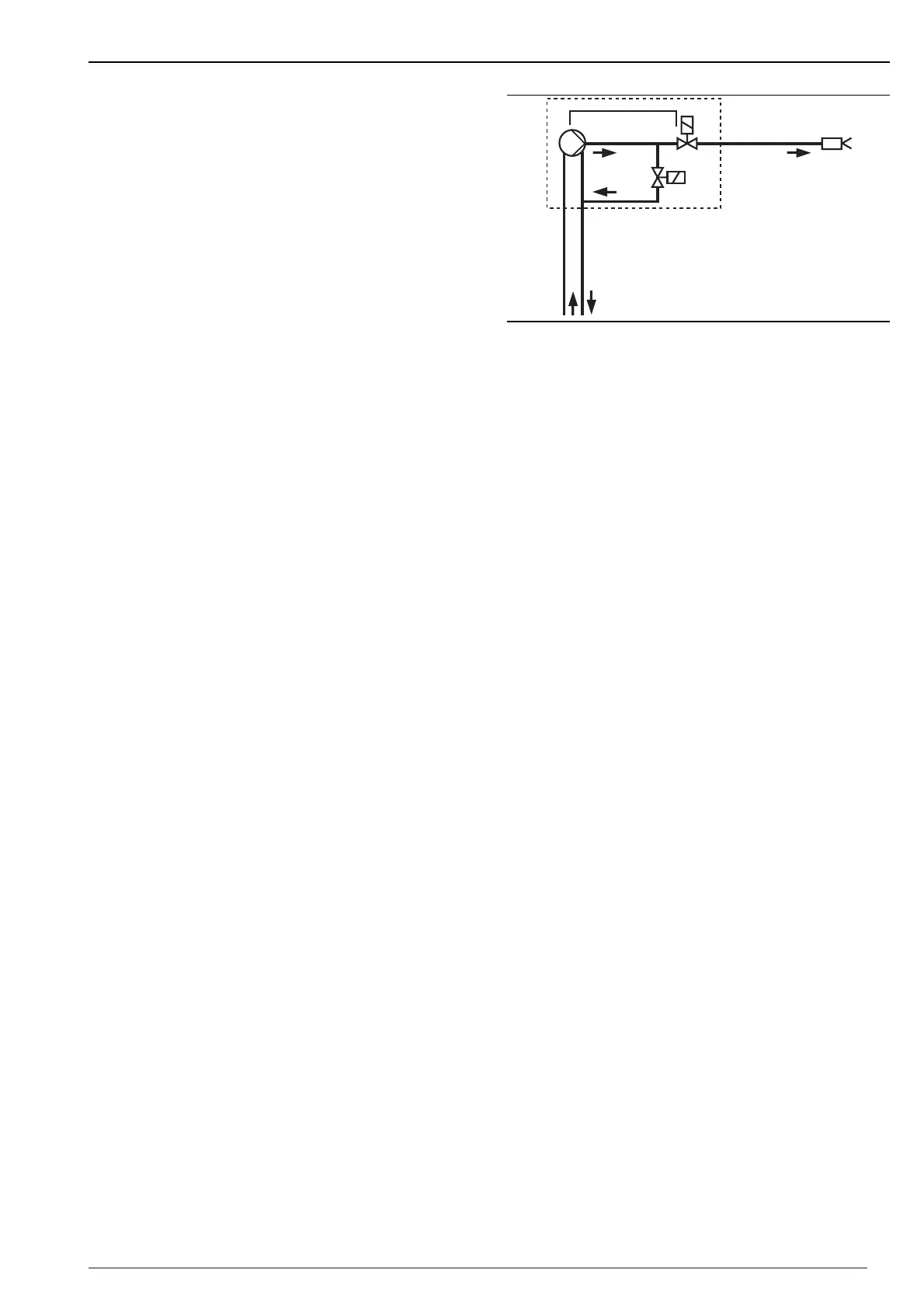
Nozzle assembly
• The total oil throughput required is provided by a single
nozzle.
• The diffuser is set as required with the setting screw.
Sequence of operations
Demand for heat from the appliance’s controller:
• Fan start - pre-purge of the combustion chamber
• Ignition on
• Servomotor drives to partial load
• Solenoid valve stage 1 opens after prepurge - fuel
release
• Flame formation
• Depending on the heat required, the servomotor drives
to full load following a waiting time of approx. 5
seconds, opens the air damper and releases solenoid
valve 2.
• After 24 hrs. of continuous operation a controlled
shutdown is carried out.
Controlled shut down:
Solenoid valve closes
• Post-purge of the combustion chamber
• Burner switches off - Standby
 Loading...