EasyManuals Logo

Weishaupt WL10/2-C Z User Manual

Weishaupt WL10/2-C Z
36 pages
To Next Page IconTo Next Page
To Previous Page IconTo Previous Page
Page #18 background imageLoading...
Page #18 background image
18
3
11
6
4
1
5
13
12
X6 + X7
F7
K3
K1
K3
K2
K4
K5
X5:1
X3:6
X3:1
X3:5
X3:12
X3:13
X3:4
X3:11
X3:3
X4:1
X7X6
A1
L PE N T1 T2 S3 B4 B5 T6 T7 T8
F7
M
Y20 C1 T1
M1
M
~
B1
F2
F1
P2H3P1
H2
H1
F3
S1
h
h
F4
LPEN
230V 1/N/PE 50/60Hz
max.
16A
Y11 Y14
S2
X9
P
ϑ
P
ϑ
P
ϑ
Y12
W-FM10
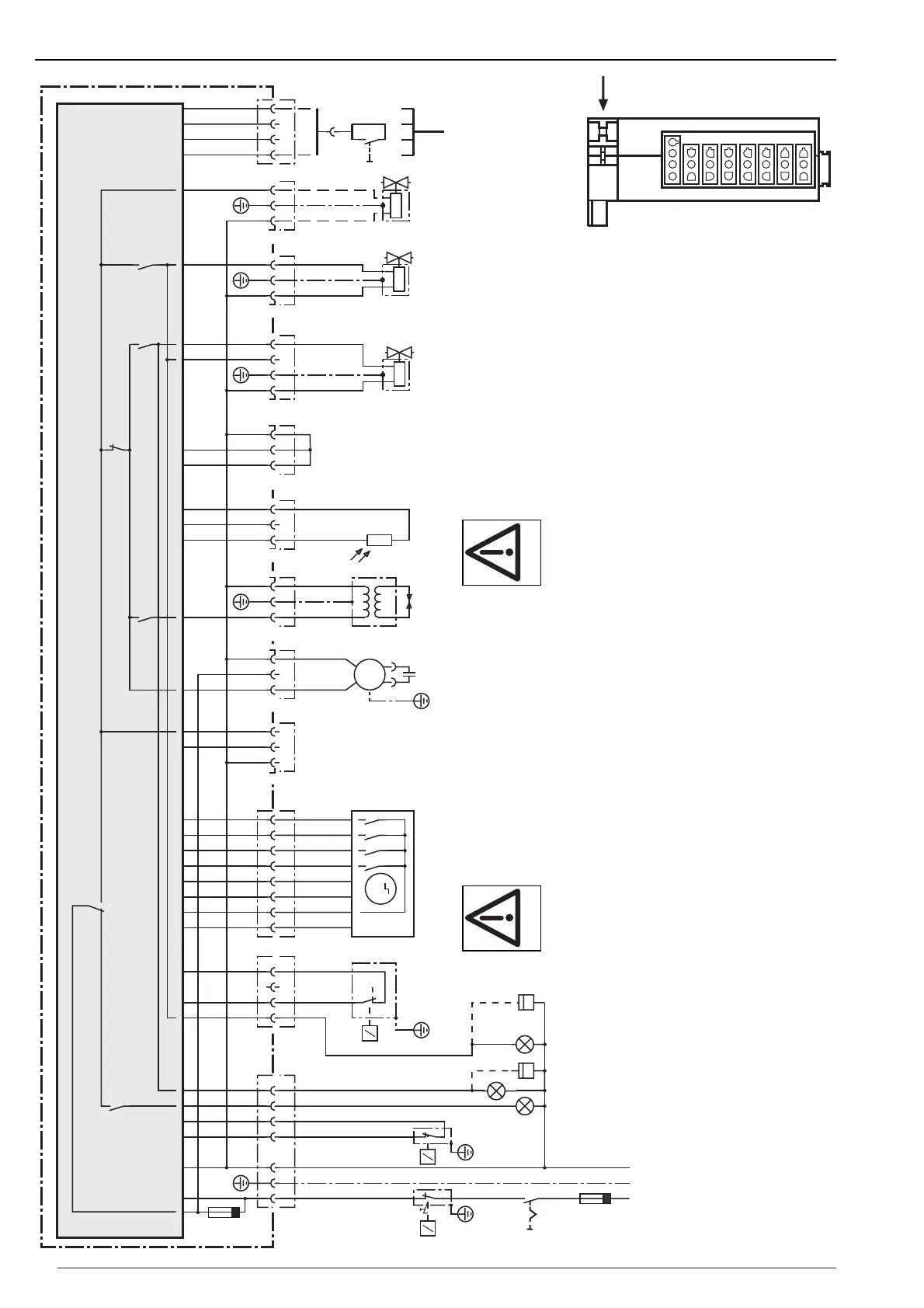
Wiring diagram WL10/2-C, vers. Z
A1 W-FM10 combustion manager with plug
connectors
B1 Flame sensor
C1 Motor capacitor
F1 External fusing (max. 16A slow)
F7 Internal fuse (max. 6·3A slow)
F2 Temperature / pressure limit controller
F3 Temperature / pressure control
F4 Temperature / pressure control full load
H1 Fault lamp
H2 Operation lamp
H3 Operating lamp full load
M1 Burner motor
P1 Hours run meter (optional)
P2 Hours run meter full load (optional)
S1 Main switch
S2 Remote reset (optional)
T1 Ignition unit
X3 Plug console
X4 Printed circuit boards - direct plug
(stepping motor)
X5 Printed circuit boards - direct plug
(Bus/S2)
X6, X7 Burner connection plug
Y11 Solenoid valve partial load
Y12 Solenoid valve full load
Y14 Anti siphon valve / tank valve (optional)
Y20 Air damper servomotor
Bus
interface
W-FM10
Combustion managers
are safety devices.
Do not open!
DANGER
Earthing and neutral to
local regulations.
Air
Installations deviating from the
wiring diagram are not permitted
DANGER

Questions and Answers:

Question and Answer IconNeed help?

Do you have a question about the Weishaupt WL10/2-C Z and is the answer not in the manual?

Weishaupt WL10/2-C Z Specifications

General IconGeneral
BrandWeishaupt
ModelWL10/2-C Z
CategoryBurner
LanguageEnglish

Related product manuals