4. Description of inputs and outputs
4.1 Inputs
Terminal 1: Rotation direction
LOW Direction of rotation CW (right)
HIGH Direction of rotation CCW (left)
The signal must appear on the rising/leading edge of cam and the direction of rotation must be determined
(Output “C“ or “E“).
Terminal 2: Enable (RESET/Stop)
It is absolutely necessary to wire this input.
LOW - Disable (Motor STOP)
- Reset Alarm
HIGH Enable
At LOW all drive movements are locked (including manual mode).
Outputs “C“ and “E“ (motor contactor) and output “D“ (brake) are switched off immediately.
Danger!
Input “Terminal 2“ on the control card alone does not full the requirements
for the specication of EMERGENCY STOP and door circuits as it requires a
functioning wiring. In order to achieve the full EMERGENCY STOP functionality,
“Terminal 2“ and the motor line must be interrupted.
Terminal 3: Start (edge triggered)
A LOW/HIGH edge starts a complete cycle. The start impulse must have a minimum width of 20 msec. A permanent
signal will not trigger a new start.
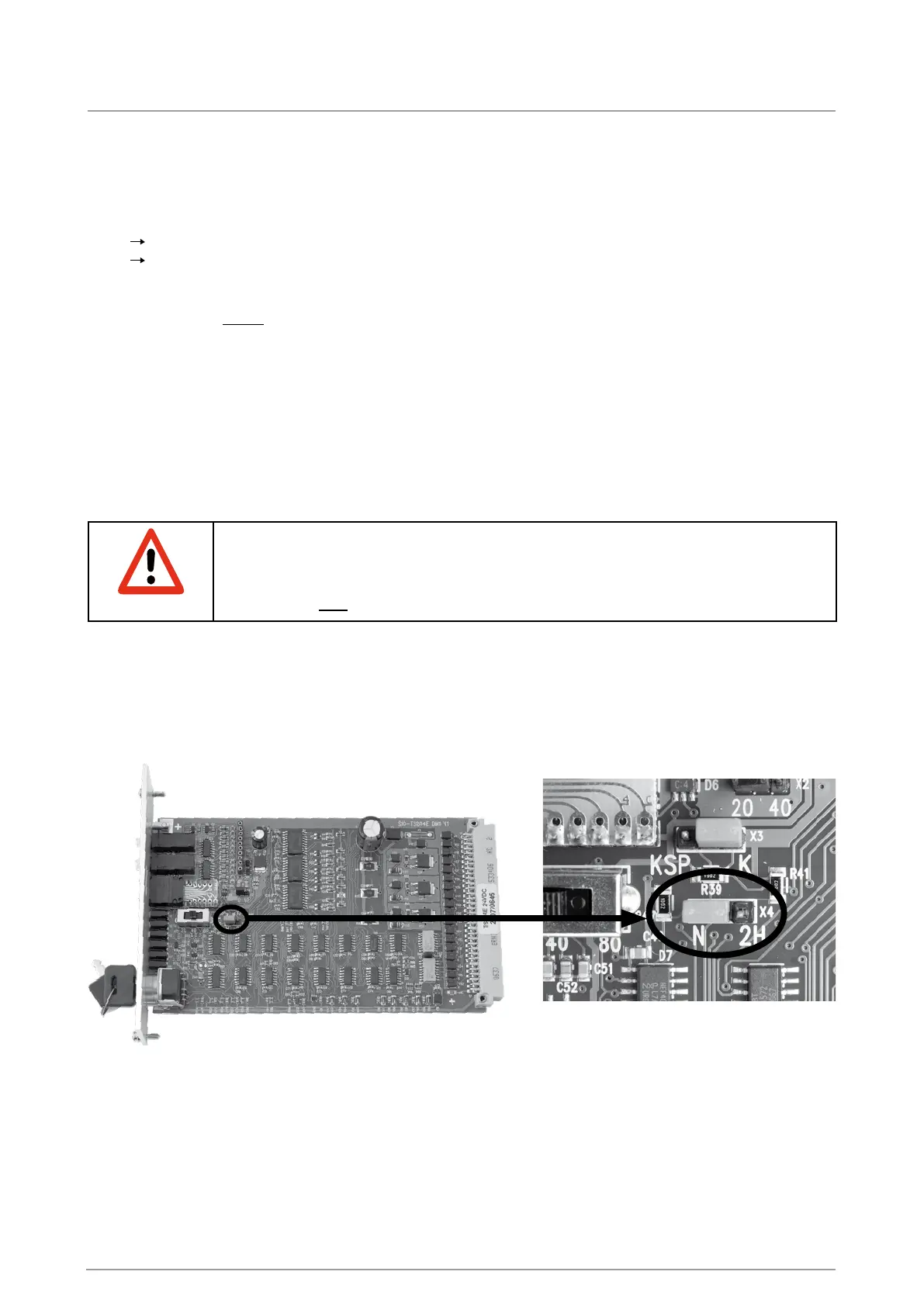
The jumper “N-2H“ must be inserted on the left. The terminal “H“ has no effect.
Terminal 5: Stop
A HIGH level causes suppression of the start signal and an interruption of the drive movement.
Terminal “F“: Sensor
The connection of the sensor to the rotary indexing table. It signals when the cam has been reached and triggers a
motor STOP.