3. Installation
Page 16 104781 - MRF-2 | MRH-2 - V2.4 - 22.07.2020
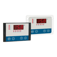
MRH-2
For fixing the housing please follow the instructions:
Place the seal carefully in the groove. Ensure it is not twisted.
Push the housing onto the stud bolts from behind.
Fasten the housing by using the hex nuts provided..
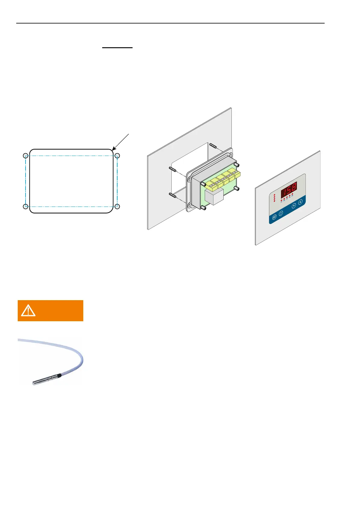
3.4 Fitting the sensor
The sensor cable must not be chafed or kinked.
Do not place the sensor and the high-voltage cable in the same cable
conduit (not even within the switchbox).
The MRF-2 | MRH-2 has been designed for connection to various types of sensor
(see technical data). It can function properly only if one of those sensor types is
installed and the parameters are correctly set.
When setting the temperature controller parameters (and whenever the sensor is
replaced) the “actual value correction” [Parameter C91] must be adjusted so that the
temperature measured corresponds to that shown on the display. A reference ther-
mometer should be used for this purpose.
See the section Fehler! Verweisquelle konnte nicht gefunden werden. "Setting
the actual value correction".
Pay attention to the permitted temperature range for sensor cable exposure.
Panel cutout
87,5 x 66,5 mm
Pin size welding studs M3
96 x 53 mm
 Loading...