5. Operation
104781 - MRF-2 | MRH-2 - V2.4 - 22.07.2020 Page 23
5.4.1 Explanation of controller and function blocks
Explanation controller block 1 + 2
Parameter [P11 + P12] you determine:
which type of control - 2-step-regulation
- PID pulsed
- PID analogue
which input - Sensor 1 to 3 (2 sensors also possible)
- analogue input
link - Absolute value control on sensor
- Difference temperature control
- Control with external setpoint specification
Adjustment see parameter list.
The setting for which OUTPUTS are to be controlled is defined on the rele-
vant relay or the analogue output [parameters P21-P27].
Explanation controller block 3 + 4
Parameter [P13 + P14] you determine:
which type of control - only 2-step-regulation possible
Everything else same as controller block 1.
Explanation function block temperature alarm 1 + 2
Parameter [H1 + H2] you determine:
which alarm type - band alarm
- limit alarm
- High or low temperature alarm
- each with relative or absolute
which input - controller block 1 to 4
link - act directly on relays
- act on controller block
- message on fault indicator
Adjustment see parameter list.
The setting for which OUTPUTS are to be controlled is defined firstly in
parameters [H5 + H6] and secondly on the relevant relay [parameters P21-
P25].
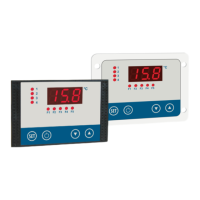
Controller block 1 [P11]
may be: - 2-step-regulation
- PID pulsed
- PID analogue
Sensor input 1
Sensor input 2
Sensor input 3
analog input
Relay K1
Relay K2
Relay K3
Relay K4
Relay K5
analog input
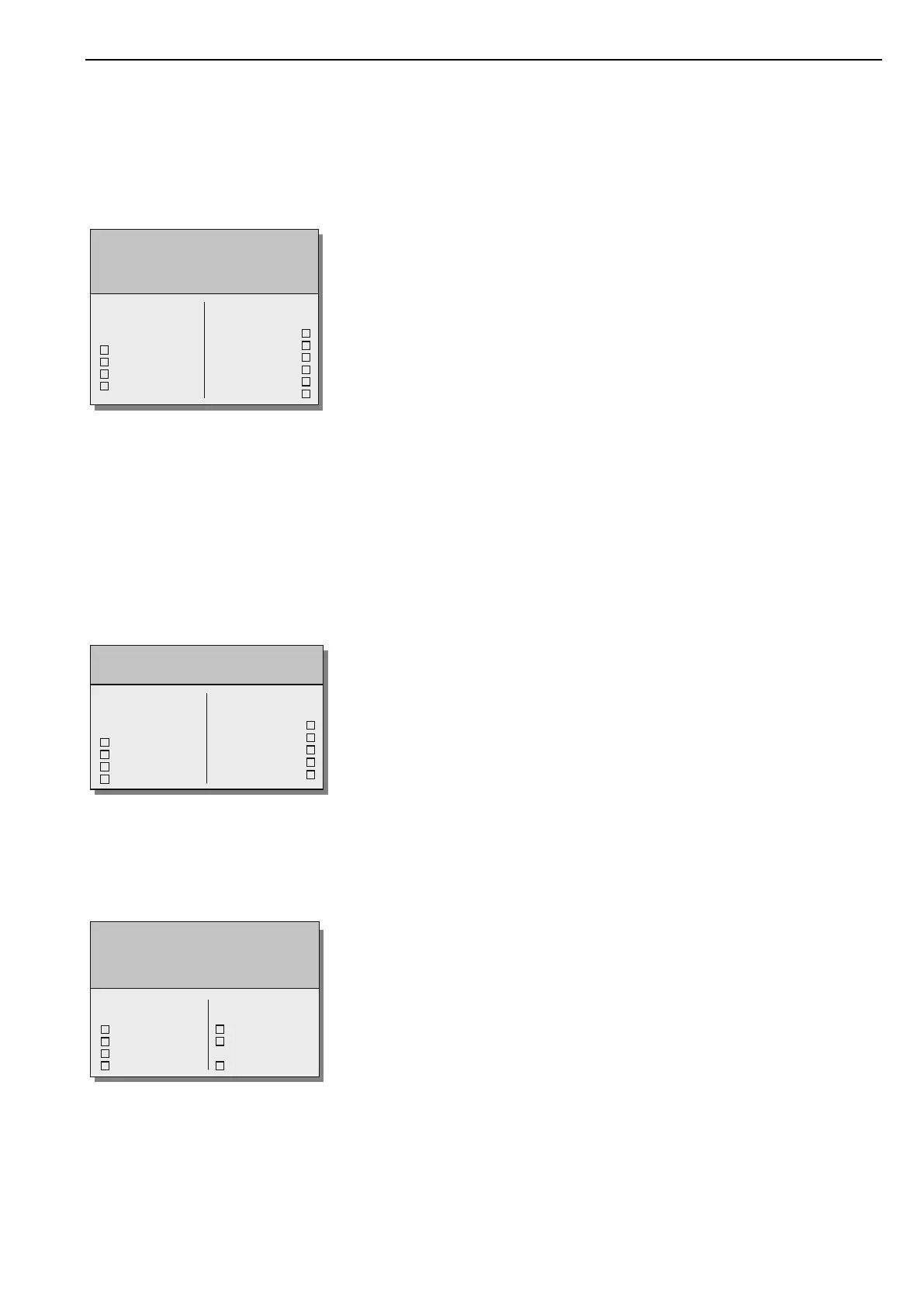
Controller block 3 [P13]
is always: - 2-step-regulation
Sensor input 1
Sensor input 2
Sensor input 3
analog input
Relay K1
Relay K2
Relay K3
Relay K4
Relay K5
Func. temperature alarm 1 [H1]
may be: - act directly on relays
- act on controller block
- message on fault indicator
Controller block 1
Controller block 2
Controller block 3
Controller block 4
Relay K1 .. K5
Controller block
1 .. 4
Fault indicator
 Loading...