6. Other information
Page 44 104781 - MRF-2 | MRH-2 - V2.4 - 22.07.2020
6.3 General measures when using electronic control systems
So that even complicated regulatory tasks can be presented to the user in a manner
which is clear and simple and ensures high measurement accuracy, today's electro-
nic control systems make increasing use of microprocessors. However, the benefits
of these systems are countered by the disadvantage that increased measurement
accuracy is accompanied by sensitivity to interference. In order to minimise the effect
which interference may have on the regulator the user also must take account of a
number of points when installing a new regulator.
Assistance here is provided by standard DIN VDE 0843 on the electromagnetic com-
patibility (EMC) of measurement, control and regulatory devices in industrial process
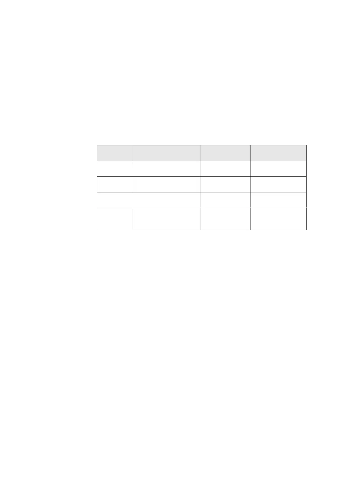
technology. The following table shows, for example, the maximum interference le-
vels to which (according to the standard), an appliance may be exposed.
Test voltage
Power supply
Test voltage
Signal/control line
well-protected
environment
typical industrial
environment
industrial environment
with very high
interference level
As the values given in the table are maximum values, operational values should
remain well below them. However, in practice this is possible only with difficulty, as
even a normal contactor without interference suppression produces interference pul-
ses of up to 3.0 kV. For this reason we recommend that the following principles be
taken into account during installation:
a. Versuchen Try to eliminate all sources of interference by carrying out interfe-
rence suppression and minimising the interference level. Radio interference
suppression is required under VDE 0875 and confirmed by VDE 0874. In prin-
ciple the interference must be eliminated at source. The nearer the interference
suppresser is to the source of interference the greater its effect.
Interference spreads through wires or by electromagnetic radiation. It is usually
the former which interferes most seriously with regulation systems..
Possible interference sources (to name a few) include:
bouncing contacts when switching loads
switching off inductive loads (contactors, motors, solenoid valves, etc.)
unsatisfactory routing of wires, too small cross-sections
loose contacts
rhythmically changing power stages (power converters)
power breakers
high-frequency generators
 Loading...