5. Operation
Page 24 104781 - MRF-2 | MRH-2 - V2.4 - 22.07.2020
Explanation function block digital input 1 + 5
Parameter [H21 or H25] you determine:
which function - switches relays on and off
- triggers fault reports
- switches to alternative setpoint
- activates stand-by
which input - digital input 1 to 5
link - act directly on relays
- act on controller block
- Message on fault indicator
Adjustment see parameter list.
The setting for which OUTPUTS are to be controlled is defined firstly in pa-
rameters [H25 + H26] and secondly on the relevant relay [parameters P21-
P25].
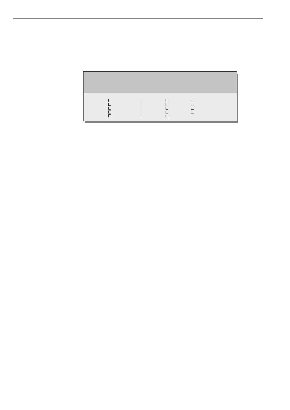
Function digital input 1 .. 5 [H21 - H25]
May be: - act directly on relays - switch setpoint
- act on controller block - collective fault message
- switching regulator in standby
Dig. input 1
Dig. input 2
Dig. input 3
Dig. input 4
Dig. input 5
Relay K1
Relay K2
Relay K3
Relay K4
Relay K5
Controller block 1
Controller block 2
Controller block 3
Controller block 4
 Loading...