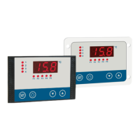
5. Operation
Page 30 104781 - MRF-2 | MRH-2 - V2.4 - 22.07.2020
Lower limit temperature
Lower limiting of difference temperature control.
(Switchover to absolute value control when reached).
Upper limit temperature
Upper limiting of difference temperature control.
(Switchover to absolute value control when reached).
[C30 .. C31] are visible only if at least one control compo-
nent is set to difference temperature with limit values.
Alarm limit for temperature alarm 1 below
Alarm limit for temperature alarm 1 up
Alarm limit for temperature alarm 2 below
Alarm limit for temperature alarm 2 up
In the case of relative limits, the values should be regar-
ded as degrees Kelvin.
[C40 .. C43] are hidden, in accordance with the alarm set-
tings [H3 und H4].
-99°C .. +400°C
-99°C .. +400°C
-99°C .. +400°C
-99°C .. +400°C
Actual value sensor 1
Sensor correction [C91] is entered automatically.
Sensor correction sensor 1 (offset value)
Only display value. Is entered automatically.
Actual value sensor 2
Sensor correction [C93] is entered automatically..
Sensor correction sensor 2 (offset value)
Only display value. Is entered automatically.
Actual value sensor 3
Sensor correction [C95] is entered automatically.
Sensor correction sensor 3 (offset value)
Only display value. Is entered automatically.
[C92 .. C95] are only displayed if activated in [D2, D3].
Actual value analog input
Display value. Can not be changed.
[C96] is hidden when analog input is disabled.
Displayed value, working level
This is used to determine which actual value should be
displayed in the working level as the default setting.
[C97] is in use only if more than one sensor is enabled.
1 = sensor 1
2 = sensor 2
3 = sensor 3
4 = analog input 1
Software version
Display value. Can not be changed.
Button lock in working level
When locked, the setpoints can NOT be changed in the
working level..
0 = lock on
1 = lock off
* = further details see glossary
** = For sensor correction procedure see section Fehler! Ver-
weisquelle konnte nicht gefunden werden.

 Loading...