Weldmatic 215Operators Manual
Model No. CP111-0, Iss A 02/05 9
Quality, Reliability, Performance
The quality of the consumable wire
greatly affects how reliably a gas metal
arc welder will operate. For best results
when welding mild steel, we recommend
quality WIA AUSTMIG ES6. Dirty, rusty
or kinked wire will not feed smoothly
through the gun cable and will cause
erratic welding. Deposits from the wire
will clog the gun cable liner requiring it
to be replaced prematurely.
Fitting the gas cylinder
Place the gas cylinder on the tray at the rear of
the welder. Retain the cylinder with the chain
provided.
Fit the gas regulator to the cylinder. DO NOT
apply grease or oil to these joints.
Fit the end of the gas inlet hose from the back
of the power source to the connector supplied
with the gas regulator, and secure with the
clamp also supplied.
Fitting The Gun and Cable Assembly
The supplied BERNARD gun/cable assembly is
equipped with a ‘Euro’ wirefeeder connector
which incorporates all required connection
points for welding current, shielding gas and
gun switch control.
To attach the gun/cable assembly to the
wirefeeder mechanism, engage the mating
parts of the male and female Euro connectors,
then rotate the locking ring clockwise to firmly
secure the connection.
Fitting the Consumable Wire
Place the spool of welding wire onto the spool
holder. The location pin should mate with a
hole provided on the wire spool body. Fit the
spool retaining ‘R’ clip supplied. Check the
adjustment of the spool brake, which should
be set to prevent over run of the wire spool at
the end of a weld, without unduly loading the
wirefeed motor. The braking can be adjusted
by the Nyloc nut using a 15/16” AF or 24mm
socket wrench.
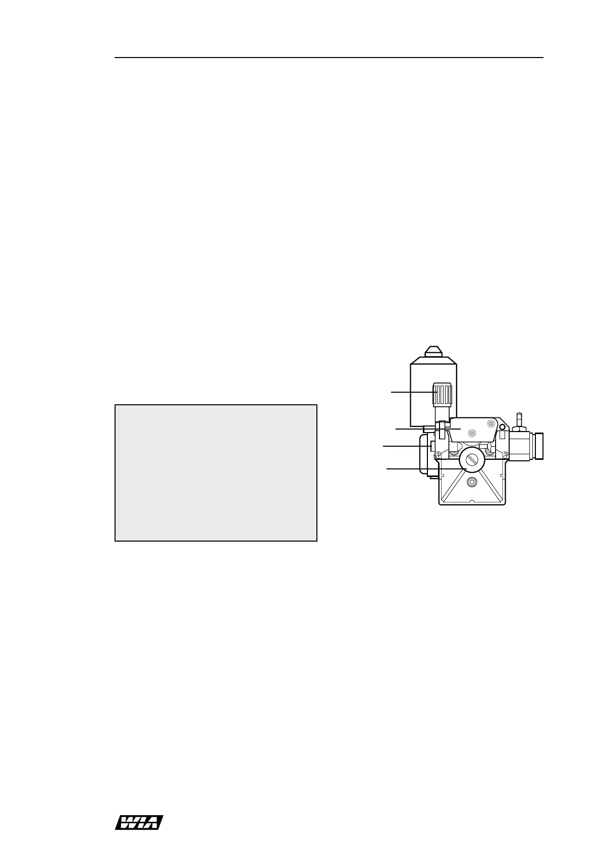
Feeding the Consumable Wire
At the wirefeed assembly, release the
compression screw and rotate the top roller
arm to the open position. The end of the
welding wire can now be passed through the
inlet guide, over the bottom driven roller, and
into the output wire guide tube. Check that the
drive roll groove is correct for the wire in use.
The appropriate size is stamped on the visible
side of the installed roller. Check also that the
correct size contact tip is fitted at the gun end.
Feed roller and tip details are shown in Section
11 of this manual.
Return the pressure arm to the closed position
and adjust the compression screw to provide
sufficient clamping of the drive roll to achieve
constant wirefeed. Do not over tighten.
With the equipment energised, operate the
gun switch to feed wire through the gun cable.
Compression
screw
Top roller arm
Inlet guide
Groove size
0.9