Cod.006.0001.1440
03/06/2013 v2.2
ENGLISH
0
5/28
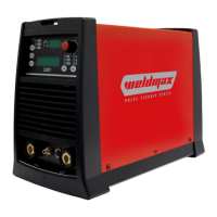
3 REAR PANEL
1: Welding power source ON/OFF switch.
2: Remote controller connector.
3: Connector for gas feed hose:
cylinder power source
4: Power cable.
Total length
(including internal part)
Number and cross section of wires
5: Cooler power feeding connector.
IP20 (cap open)
IP66 (cap closed)
If the socket is not connected to any devices always close the cap:
presence of hazardous voltage levels!
4 INSTALLATION
WARNING!
Lifting and positioning
Read the warnings highlighted by the following symbols in the
“General prescriptions for use”.
4.1 CONNECTIONS TO THE ELECTRICAL MAINS
NETWORK
The characteristics of the mains power supply to which the equipment
shall be connected are given in the section entitled “technical data” on
page 23.
The machine can be connected to motorgenerators provided their
voltage is stabilised.
Connect/disconnect the various devices with the machine switched
off.
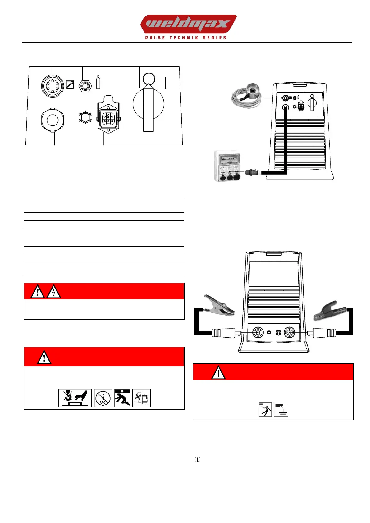
4.2 PREPARING FOR MMA WELDING
1. Set the welding power source ON/OFF switch to “O” (unit de-
energized).
2. Plug the power cable plug into a mains socket outlet.
3. Choose the electrode based on the type of material and thickness
of the workpiece to be welded.
4. Insert the electrode in the electrode holder.
5. Connect the electrode holder clamp plug to the following welding
socket: Positive pole welding socket.
6. Connect the earth clamp plug to the following welding socket:
Negative pole welding socket.
7. Connect the earth clamp to the workpiece being processed.
WARNING!
Electric shock hazard!
Read the warnings highlighted by the following symbols in the
“General prescriptions for use”.
8. Set the welding power source ON/OFF switch to “I” (unit
powered).
9. Select the following welding mode on the user interface: MMA
10. Set the required welding parameter values on the user interface.
When the remote controller [RC] is connected and the relative
locking screw is tightened, welding current can be adjusted using
the remote controller.
The system is ready to start welding.