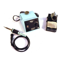
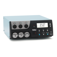
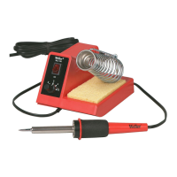
The Weller EC1002S Electronic Soldering Station is a precision tool designed for electronic soldering applications, offering reliable performance and user-friendly features. It is suitable for both professional and hobbyist use, providing controlled heat for delicate components.
Function Description
The EC1002S is an electronic soldering station that provides controlled heat to a soldering iron tip for joining electronic components. It utilizes a high-precision platinum RTD (Resistance Temperature Detector) sensor in its soldering tools (EC1201A, EC1302A, EC1503A) to ensure accurate temperature control. The power unit is factory calibrated, but can be checked and re-calibrated using a WC1000 Calibration Reference Unit if necessary. The electronic control system delivers maximum power to the heated load, even at lower temperature settings, which helps protect sensitive components from heat damage.
Important Technical Specifications
- Power Input: 120VAC +/- 10%, 60Hz, or 230VAC +/- 10%, 50/60Hz.
- Power Consumption: 60 watts.
- Power Unit Output Voltage: Isolated 24VAC @ 2.1 amperes.
- Dimensions: 4.5" x 5.9" x 3.6".
- Line Cord: 3 wire, U.L. recognized.
- Tip Temperature Control Range: 350°F to 850°F (175°C to 455°C).
- Control Setting Resolution: 10°F (5°C).
- Stability: +/- 10°F (+/- 6°C) per Mil-Std-2000.
- Absolute Accuracy: Average tip temperature is calibratable to +/- 9°F (+/- 5°C) at idle with no load.
- Ambient Temperature Range: 60°F to 110°F (16°C to 44°C).
- Housing Material: Electrostatic Protective Material, meeting Mil-B-81705 requirements.
- Static Decay Test: Passes Federal Test Method Std. No. 101, method 4046.
- ESD Compliance: Weller ESD tools comply with DOD-IDBK-263.
- Certifications: UL listed, meets DOD-STD-2000, Mil-Std-2000, Mil-S-45743, W-S-6536, W-S-570, DOD-STD-1686.
Usage Features
The EC1002S is designed for ease of use and optimal soldering performance.
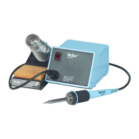
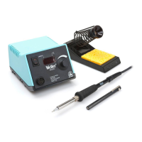
- Setup: The unit is unpacked, and the spring and funnel are placed in the tool stand. The tool stand can be attached to either side of the power unit. A reservoir is filled with water (distilled water preferred) to wet the sponge. The soldering tool is inserted into its holder, and its plug is connected to the power unit's receptacle, then locked into place. The line cord is plugged into a grounded AC receptacle, and the station is turned on.
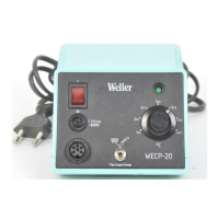
- Temperature Control: The temperature control knob allows users to set the desired tip temperature. It is recommended to approach the desired temperature by turning the knob counter-clockwise (CCW).
- Initial Use: After setting the temperature, a 30-second warm-up period is required. The tool is then removed from the holder, and the tip is tinned with solder, making the unit ready for use.
- Optimal Temperature Selection: Users are advised to always use the lowest temperature that can handle the soldering load. The electronic control ensures maximum power delivery even at low settings, eliminating the need for high temperatures for heavy loads. This practice, combined with proper tip style selection, protects sensitive components from heat damage.
- Safety: A crucial safety warning states not to remove the ground prong from the line cord plug, as this can cause erratic tip temperature control.
Maintenance Features
The EC1002S includes features for calibration and troubleshooting to ensure long-term accuracy and functionality.
Calibration Check
- Procedure: To check calibration, the tool receptacle on the power unit is connected to a WC1000 Calibration Reference Unit, selecting resistor "B". The power unit should not be turned above 350°F (175°C) for more than 1 minute with the tool connected to the WC1000 to prevent damage.
- Temperature Setting: The temperature control knob is rotated fully CCW, then turned on. After a 30-minute warm-up, the knob is rotated fully CW, and indicator lamps should be full on. Then, the knob is set CCW until indicator lamps start flashing, indicating the temperature setting. The continuous rotation temperature set knob CCW until lamps just stop flashing should correspond to 745°F ±10 (395°C ±6). If the indicator lamps have started flashing approximately 35°F (19°C) higher, resistor "A" on the WC1000 is selected, and the temperature set knob CCW until indicator lamps just stop flashing should correspond to 395°F ±10 (200°C ±6). If calibration is out of tolerance, a re-calibration procedure is required.
Tip Temperature Calibration Procedure
- Monitoring: Monitor the tip temperature with a 30-gauge thermocouple resistance welded to the center of the wetted area. Tinning should be removed before welding. K-111, K-121, and K-131 temperature test kits are recommended.
- Adjustment: Set the temperature set knob to the desired temperature and allow the tip temperature to stabilize. Adjust R10 (a potentiometer on the circuit board) through the hole in the station bottom directly below the temperature set knob, until the indicated tip temperature matches the set temperature.
Re-calibration Procedure
- Disassembly: The power unit must be disassembled to gain access to the calibration adjustments. This involves removing four rubber feet and screws, then lifting the top cover. The front panel is disengaged from the base, and the control board is lifted to access the calibration pots (R24 and R25).
- Adjustment: With the power unit on and after a 30-minute warm-up, connect the WC1000 Calibration Reference Unit to the tool receptacle and select resistor "B" (without a tool connected). Connect a tool to the WC1000 as a load and adjust R25 until indicator lamps just stop flashing. Then, set the knob CCW to 395°F (200°C), select resistor "A" on the WC1000, and adjust R24 until indicator lamps just stop flashing.
- Reassembly: After adjustment, turn off the power unit, disconnect the power cord and WC1000. Re-position the board, secure the temperature set pot with its washer and nut, install the temperature set knob, re-position the front panel on the base, and finally install the top cover with its screws and rubber feet. A calibration check should be performed to verify calibration.
Troubleshooting Guide
- Safety Warning: AC line voltage is present inside the power unit even when the power switch is off. Service should be referred to qualified personnel.
- Access to Internal Parts: Gained by removing four rubber feet, four screws under the feet, and the top case.
- Tool Does Not Heat:
- Check for approximately 21 ohms at line cord blades (55 ohms for 230V units) with the line cord unplugged and power switch on.
- Check and replace the fuse (0.6A for 120V, 0.3A for 230V slow blow fuse) located on the bottom of the case.
- Check and replace the power switch if defective.
- Check and repair/replace the line cord if defective.
- Check and replace the transformer primary if defective.
- Tool Overheating:
- Troubleshoot the soldering tool using the guide in the tech sheet.
- Replace the printed circuit board assembly in the station.
- Tip Temperature Testing Errors:
- Ensure the thermocouple wire is resistance welded to the center of the wetted area on the tip, with tinning removed.
- Other methods or heavier thermocouple wire may cause errors. K-111, K-121, and K-131 temperature test kits are available.
- Troubleshoot the soldering tool using the guide in the tech sheet.
- Calibrate the station according to the Tip Temperature Calibration Procedure.
- High Tip Voltage:
- Troubleshoot the soldering tool using the guide in the tech sheet.
- Check for continuity from pin #5 of the tool receptacle to the line cord ground pin.
- Check wiring from the tool receptacle to the line cord ground pin and repair if defective.
Available Models and Hand Pieces
The EC1002S series offers various models and compatible hand pieces:
- EC1002S-0: Power unit only, 120V 60Hz, °F dial markings.
- EC1002S-0D: Power unit only, 230V 50/60Hz, °C dial markings.
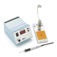
- EC1002S-1: Power unit, 120V 60Hz, °F dial markings, EC1201A tool with ETA tip, and tool stand.
- EC1002S-1D: Power unit, 230V 50/60Hz, °C dial markings, EC1201A tool with ETA tip, and tool stand.
- EC1002S-2: Power unit, 120V 60Hz, °F dial markings, EC1302A tool with EPH101 tip, and tool stand.
- EC1002S-2D: Power unit, 230V 50/60Hz, °C dial markings, EC1302A tool with EPH101 tip, and tool stand.
- EC1002S-3: Power unit, 120V 60Hz, °F dial markings, EC1503A tool with EMA tip, and tool stand.
- EC1002S-3D: Power unit, 230V 50/60Hz, °C dial markings, EC1503A tool with EMA tip, and tool stand.
Compatible Soldering Tools:
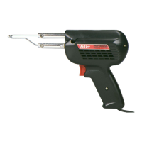
- EC1201A: 40 watt soldering tool w/ETA tip.
- EC1302A: 20 watt soldering tool w/EPH101 tip.
- EC1503A: 42 watt high capacity soldering tool w/EMA tip.
Replacement Parts and Accessories
A comprehensive list of replacement parts and accessories is available, including:
- Power Switch: SW110
- Receptacle and wire harness: EC270
- Circuit board assembly: EC271
- Power transformers: TR234 (120VAC), TR235 (230VAC)
- Fuses: FP3 (6 AMP Slo Blo), FP3D (315mA for 230VAC models)
- Sponge: TC205
- Desoldering adapter kit: DS200K
- Spring and funnel for various tools: TC204 (EC1201A), IHF225EC (EC1302A), EC254 (EC1503A)
- Soldering tools with Fume Extraction attachment and stand: EC1201AP, EC1302AP, EC1503AP
- Tool funnel for SMT tips: SF60
- Surface mount tip adapters: SMTA (EC1201A), SMTA-EM (EC1503A)
- Calibration Unit: WC1000
- Soldering Tool Analyzer: WA2000
- WELLER® Polishing Bar: WPB1
- Temperature test kits: K-111 (EC1201A), K-121 (EC1302A), K-131 (EC1503A)
The Weller EC1002S is a robust and versatile soldering station designed to meet the demands of precise electronic work, backed by detailed instructions for setup, operation, calibration, and troubleshooting.