Sp
ec
ifications
I. Power input:
12
0VAC +!- 10%, 60
1l7.
, (230VAC
t/
-
10
%, 50!60
Hl
.).
60
wa
lls
2. Power unit output vo!tJgc: isolated
24
VAC
@
2.1
amp
cn.:
s.
3.
Si~e
:
4.5" x 5.9" x 3.6"
4. L
in
e
C<>
rd
· 3 wire. U
1..
recogni~.:d
5. Tip
tc
mpcr:.turc control r:.ngc:
3SO
"F to
850°1'
( 1
75
"C
to
-<55
°C).
6. Control selli
ng
rc
$o
lution· I
O"F
(5"C).
7.
Stabilit
y.+/-
J
O"
F (+I- 6"C) per Mii-Std-2000.
!!. Absolute accuracy: Average tip
temperatur<.:
is calibratablc
to+
/-
<J°F
(+/-
S°C) at idle with no load.
9.
Ambi
cmtem
peraturc range: 60''F to 1!0°
1'
(1
6"C
to
44°C}
I 0. Housing made with Electrostatic Protective Material as required
in
1\
lil-B-81705.
II. H
ou,
in
g pass.:s Static Decay
te
st per Federal Test Method Std. No. I 0 I, method 4046.
12.
Weller' ESD tools co
mpl
y
wi
th DOD·I
IDG
K-263
13.
EC1
002S units arc
UL
li
sted
ami
meet DOD-STD-2000, Mii-Stu-2000,
1\lii
-S
-4
5743,
W-S
-6536,
W-S-570, DOD-STD-1686.
Materials Needed For Calibration
Ch
eck
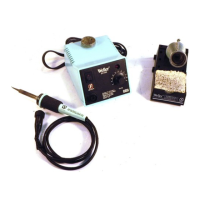
The EC 1
20
I A, EC 1302A
and
EC J 503A soldering t
oo
ls u
se
high precision
platinum RTD temperature sensors and therefore require
no
calibration
and
are
i
nt
erchangeable.
The
po
wer
unit is fac
tor
y calibrated; but can easily be checked
usi
ng
a
WC
I
000
Calibration Reference Unit and re-calibrated if required.
Cl
D
CJ
oQ
Cl
ju2j
CJ
CJ
CJ
~~~
Cl
CJ
Cl
D
CJ
[)
Cl
R25
CJ
R24
D
G
Cl
D
CJ
D
01
Cl
Dl
CJ CJ
CJ
CJ
D
CJ
Cl
D
Cl
01
CJ
P1
CJ
8455
R10
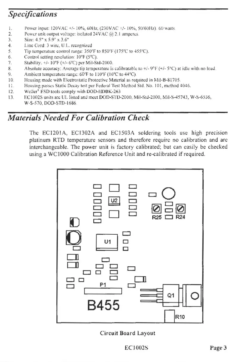
Ci
rcuit
B
oa
rd
Layo
ut
EC 1002S Page 3