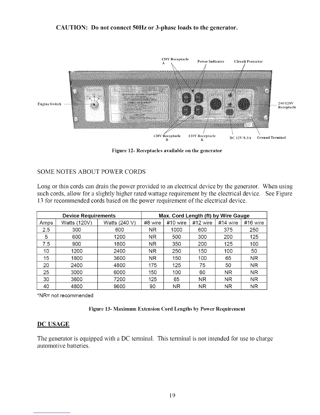
CAUTION: Do not connect 50Hz or 3-phase loads to the generator.
120V Receptacle Power Indicator Circuit Protector
A
Engine Switch
240/120V
Receptacle
120V Receptacle 120V Receptacle DC 12V/8.3A Ground Terminal
B B
Figure 12- Receptacles available on the generator
SOME NOTES ABOUT POWER CORDS
Long or thin cords can drain the power provided to an electrical device by the generator. When using
such cords, allow for a slightly higher rated wattage requirement by the electrical device. See Figure
13 for recommended cords based on the power requirement of the electrical device.
Device Requirements
Amps Watts (120V)
2.5 300
5 600
7.5 900
10 1200
15 1800
20 2400
25 3000
30 3600
40 4800
*NR= not recommended
Watts(240 V)
600
1200
1800
2400
3600
4800
6000
7200
9600
#8 wire
NR
NR
NR
NR
NR
175
150
125
90
Max. Cord Length (ft) by Wire Gauge
#10wire #12wire #14 wire #16 wire
1000 600 375 250
500 300 200 125
350 200 125 100
250 150 100 50
150 100 65 NR
125 75 50 N R
100 60 NR NR
65 NR NR NR
NR NR NR NR
Figure 13- Maximum Extension Cord Lengths by Power Requirement
DC USAGE
The generator is equipped with a DC terminal. This terminal is not intended for use to charge
automotive batteries.
19
 Loading...