ASSEMBLY & ADJUSTMENTS
10
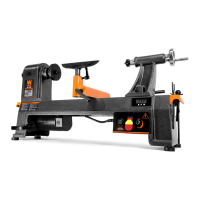
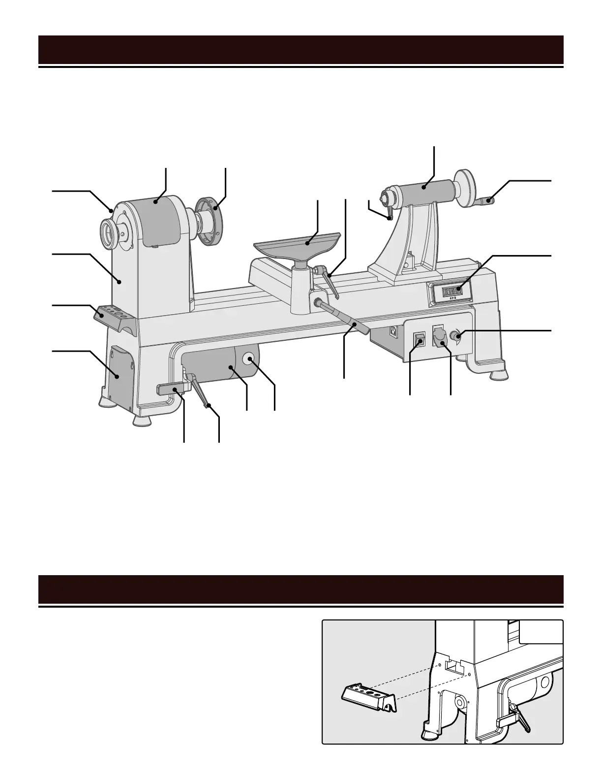
KNOW YOUR LATHE
10 10
TOOL PURPOSE
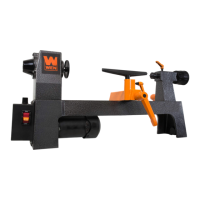
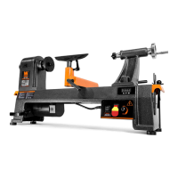
Lathes are tools that turn your workpiece so you can cut, shape, and sand them. Refer to the following diagrams
to become familiarized with all the parts and controls of your Lathe. The components will be referred to later in the
manual for assembly and operation instructions.
INSTALL THE HANDLES (FIG. 2)
Your lathe comes with a handle kit that can be used for car-
rying the lathe, as well as for tool storage.
1. Use the included hex wrench to remove the two socket-
head cap screws from either end of the lathe bed.
2. Position the handle on the bed of the lathe. Align the
mounting holes in the handle with those in the bed. Insert
and tighten the two screws using the included hex wrench.
A. Lower Belt Drive Plate
B. Handle/Tool Holder
C. Headstock
D. Spindle Lock (on back)
E. Belt Drive Access Panel
F. Face Plate
G. Tool Rest
H. Tool Rest Locking Handle
I. Quill Locking Handle
J. Tailstock
K. Tailstock Handle
L. Digital RPM Readout
M. Speed Adjustment Knob
N. ON/OFF Switch (w/ Safety Key)
O. Direction Switch
P. Tool Rest Locking Lever
Q. Carbon Brush Cap
R. Motor
S. Motor Plate Locking Handle
T. Motor Plate Tensioning Handle
A
B
C
D
E F
T
P
O N
S
R
G I
Q
J
H
K
L
M
Fig. 2
 Loading...