8
ASSEMBLY AND ADJUSTMENTS
WARNING: Always be sure that the tool is switched off and unplugged before
adjusting, adding accessories, or checking a function on the tool.
ASSEMBLY OF GUIDE BAR AND SAW CHAIN
1. Place the saw body on a firm and level surface.
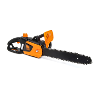
2. Rotate the bar adjust locking knob counterclockwise (Fig-
ure A - 1) to remove the cover from the saw’s body.
3. With the help of protective gloves, wrap the saw chain
around the guide bar, making sure that the teeth are aimed
in the direction of rotation. The chain should be properly set
in the slot running along the entire outside edge of the guide
bar.
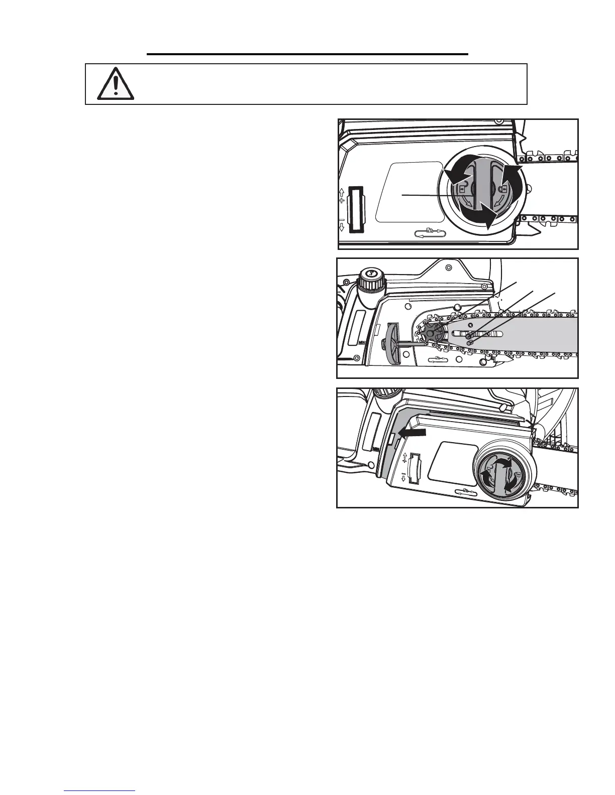
4. Place the saw chain around the sprocket (Figure B - 1)
while lining up the slot in the guide bar with the internal bolt
(Figure B - 2) at the base of the saw and the chain tension-
ing pin (Figure B - 3) in the guide bar’s pin hole. The chain
tensioning pin may need adjustment to properly align with
the hole in the guide bar. Use the chain tensioning wheel to
adjust its location until it fits in the guide bar.
5. Turn the chain tensioning wheel to preliminarily tighten
the guide bar enough that it stays in place. While holding the
bar still, place the cover back onto the saw. Make sure the tab
properly lines up with the slot on the body of the saw (Figure
C). Lock the cover in place with the cover locking knob by
turning it clockwise until it engages. Adjust tension (next).
Fig. A
Fig. B
Fig. C
1
1
2
3
TENSIONING THE CHAIN
1. Check the chain tension by pulling the saw chain away from the guide bar. A properly tensioned chain should
have roughly 1/8 inch (3 mm) of distance between itself and the bar guide (Fig. D).
2. If adjustments are needed, loosen the bar adjustment locking knob one full turn.
3. To adjust the saw chain tension, rotate the chain tensioning wheel (Fig. E). Rotating the wheel upwards increas-
es the tension while rotating it downwards decreases tension. A properly tensioned chain should have no sag (Fig.
F) and should only be able to be pulled 1/8 inch (3 mm) away from the guide bar of the saw.
4. Once the chain is properly tensioned, tighten the bar adjustment locking knob. Do not over-tension the chain:
this will lead to excessive wear and reduces the life of both the bar and chain.
NOTE: The saw chain must be tensioned properly in order to ensure safe operation. The chain tension is opti-
mal if the saw chain can be lifted 1/8 inch (3 mm) from the center of the guide bar. Since the saw chain heats up
during operation, its length can therefore fluctuate. Check the chain tension every 10 minutes of operation and
adjust as necessary, particularly for new saw chains. Slacken the saw chain after the work is completed since it
shortens when cooling down. In doing so, you can elongate the chain’s life and prevent damage.

 Loading...