88
ASSEMBLY AND ADJUSTMENTS
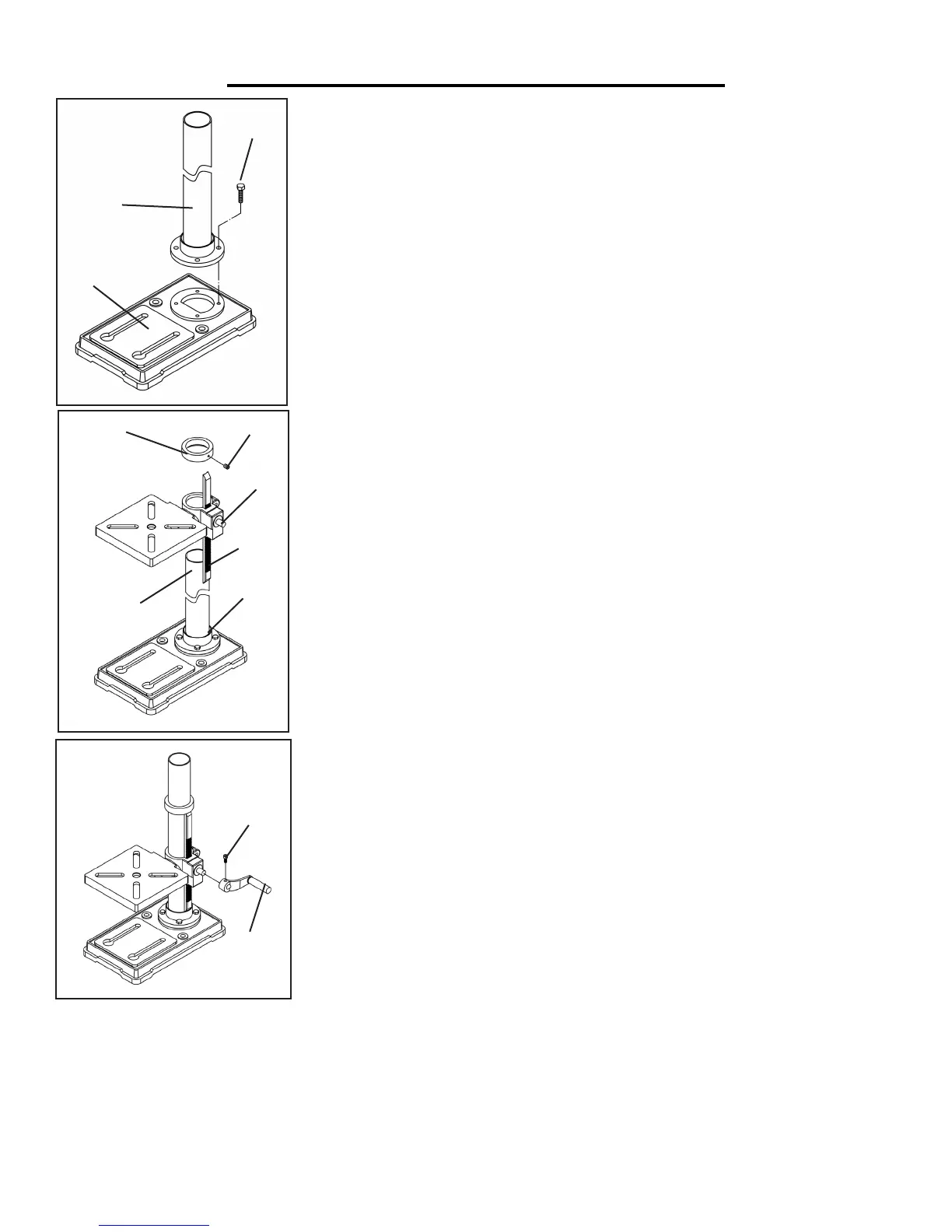
COLUMN ASSEMBLY TO BASE
1. Place the column tube (Fig. A - 2) on the base (Fig. A - 1), aligning the column
support holes to the base holes.
2. Install a hex head bolt (Fig. A - 3) in each column support hole and tighten
bolts using the adjustable wrench.
TABLE TO COLUMN
1. Loosen set screw (Fig. B - 2) in rack collar (Fig. B - 1) and remove the collar
and the rack (Fig. B - 3) from the column.
2. Insert the rack (Fig. B - 3) into the geared groove of the table assembly. Make
sure the worm shaft (Fig. B - 5) on the inside of the table support is engaged with
the teeth of the rack. The table support should sit at the center of the rack.
3. Slide the table support and rack assembly down together onto the column.
Insert the bottom edge of the rack into the lip (Fig. B - 6) of the column support.
Hold in this position until step 4 is completed.
4. Place the collar (Fig. B - 1) bevel side down over the rack. Tighten the set
screw (2) with the 3 mm allen wrench to hold the rack in position (Fig. B - 3).
Note: Make sure there is enough clearance to allow the table and rack to rotate
around the column. The collar must sit loosely over the top of the rack and not
angled on the column. To avoid column or collar damage, only tighten the set
screw enough to keep collar in place (Fig. 3).
5. Insert the table support crank handle (Fig. C - 1) into the worm gear shaft
on the side of the table support (Fig. B - 5). Make sure the set screw (Fig. C - 2)
is aligned on the flat of the shaft and as close to the table support as possible.
Tighten the set screw (Fig. C).
6. Position the table in the same direction as the base, and tighten the support
lock handle.
1
2
3
1
2
3
4
5
Fig. A
Fig. B
6
Fig. C
2
1
 Loading...