9
ASSEMBLY AND ADJUSTMENTS
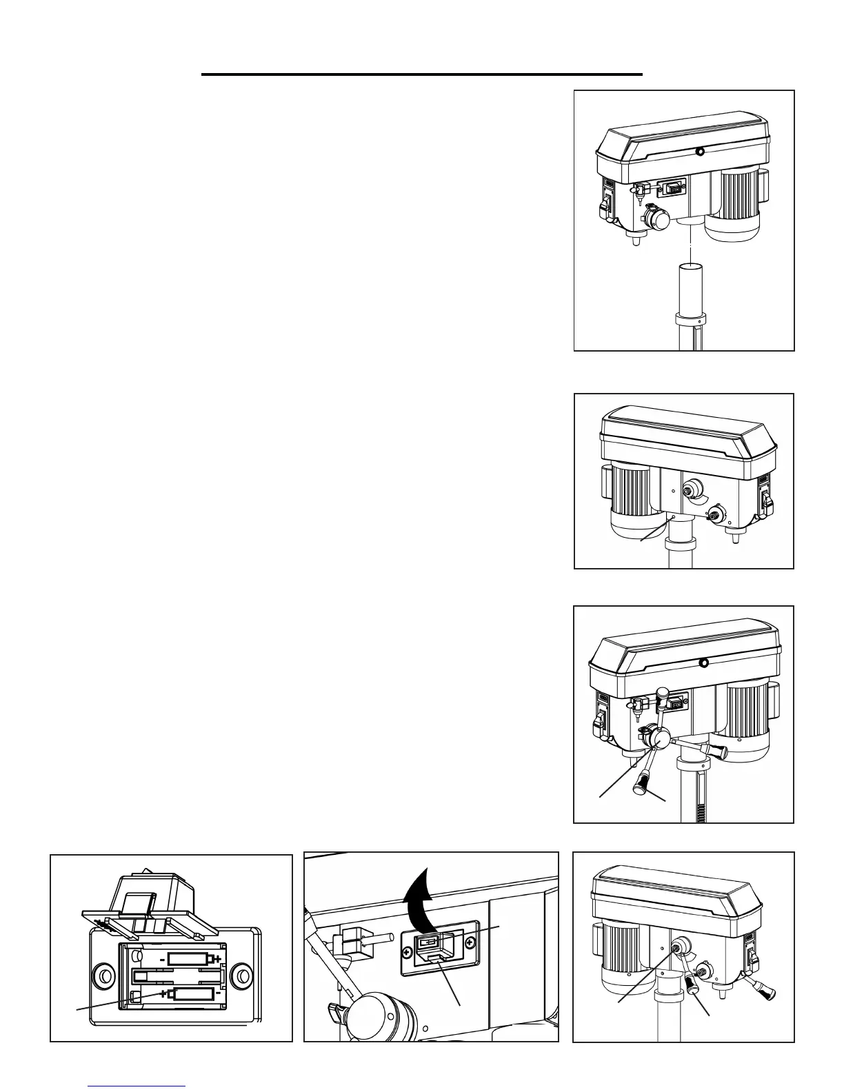
DRILL PRESS HEAD TO COLUMN
CAUTION: The drill press head is heavy. To avoid injury, two people
should lift it into position.
1. Carefully lift the drill press head assembly and position it over the column
(Fig. D).
2. Place the mounting opening on the drill press head over the top of the col-
umn. Make sure the drill press head is seated properly on the column.
3. Align the direction of the drill press head with the direction of the base and
the table.
4. Tighten the set screws (Fig. E - 1) using a hex key.
SPEED AND FEED HANDLES
1. Insert the three feed handles (Fig. F - 2) into the threaded openings on the
feed hub (Fig. F - 1). Manually tighten the handles into the openings.
Note: When using the drill press, one or two of the feed handles may be
removed if an unusually-shaped workpiece interferes with handle rotation.
2. Insert the speed adjustment handle into the threaded opening on the speed
hub (Fig. G - 1). Manually tighten handle into opening.
INSTALL THE BATTERIES
1. Make sure the laser is turned off. Press the tab (Fig. H - 1) below the laser
power switch (Fig. H - 2) and lift up the laser switch cover (Fig. I - 1).
2. Insert the two AAA batteries in the battery compartment and close the
cover. NOTE: Remove the laser light batteries when the tool is to be stored
without use for more than a few days. If left in position, the batteries run the
risk of leaking, thereby damaging the laser guide assembly. Damage due to
leaking batteries is not covered by the warranty.
1
Fig. D
Fig. E
Fig. F
1
2
Fig. G
1
2
Fig. H
Fig. I
1
2
1
 Loading...