14
ASSEMBLY AND ADJUSTMENTS
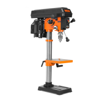
ANGULAR “PLAY” OF THE SPINDLE
Move the spindle to the lowest downward position and hold in place.
Try to make the spindle revolve around its axis while also moving it
with a side motion. If there is too much “play”, proceed as follows:
1. Loosen the lock nut (Fig. V - 1).
2. Without obstructing the upward and downward motion of the
spindle, turn the screw (Fig. V - 2) clockwise to eliminate the “play.”
Note: A little bit of “play” is normal.
3. Tighten the lock nut (Fig. V - 1).
5
1
REPLACING THE BELT
WARNING: Disconnect the drill press from the power source before replacing the belt.
Belt tension and drill press speed is controlled by automatic adjustments made to the diameter of the front spindle
when the drive handle is moved.
Note: See page 19 for information on the variable speed function of this drill press.
1. Remove the screw that secures the housing cover. Open the housing cover.
2. Remove the belt from the housing cover if it is broken. If it is not broken, but is too stretched to operate
correctly, work the belt off the drive (motor) spindle. Then remove the belt from the front spindle.
3. Replace the belt by putting a new belt over the front spindle and carefully sliding the belt over the drive (motor)
spindle.
WARNING: Do not change the drive speed when the drill press is turned off.
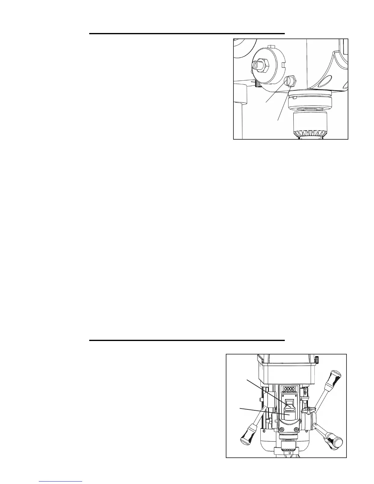
DRILL PRESS ON/OFF SWITCH (Fig. 16)
1. To turn the drill press ON, insert the yellow safety key (Fig. W -
1) into the switch housing (Fig. W - 2). As a safety feature, the switch
cannot be turned ON without the safety key.
2. Turn the switch to the ON position.
3. To turn the drill press OFF, flip the switch downward.
4. To lock the switch in the OFF position, remove the safety key
(Fig. W - 1) from the switch. Store the safety key in a safe place.
2
2
Fig. V
1
Fig. W
OPERATION
 Loading...