13
ASSEMBLY AND ADJUSTMENTS
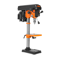
ADJUSTING THE LASER
WARNING: Do not stare directly at the laser beam. Please observe all
safety rules.
• Never aim the beam at a person or an object other than the workpiece.
• Do not project the laser beam into the eyes of others.
• Always make sure the laser beam is aimed at a workpiece that does not
possess reflective surfaces, as the laser beam could project into your eyes
or the eyes of others.
1. Place a workpiece on the table.
2. Turn the laser switch to the ON position.
3. Lower the drill bit to meet the workpiece. The two laser lines should
cross where the drill meets the workpiece (Fig. T).
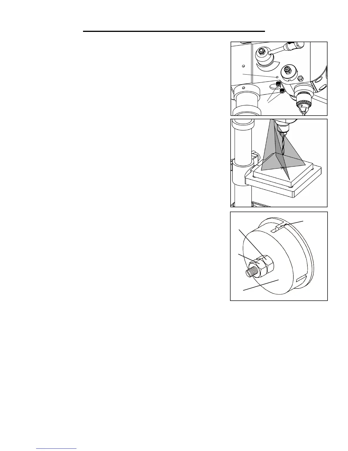
4. If the laser needs to be adjusted:
a. Loosen the hex screw (Fig. S - 1) on each side of the head and ro-
tate the laser light house (Fig. S - 2) until the lines meet in the center of
the drilled hole on the workpiece.
b. Once finished, retighten the hex screws to secure the laser.
SPINDLE RETURN SPRING (Fig. 15a)
The spindle is equipped with an auto-return mechanism located on the
lefthand side of the drill press next to the speed control handle. The main
components are a spring and a notched housing. The spring was properly
adjusted at the factory and should not be readjusted unless absolutely nec-
essary. Sometimes, however, incorrect tension causes the quill to return
too rapidly or too slowly, in which case adjustments are necessary.
NOTE: wear work gloves to prevent injury during adjustment.
Fig. Q
Fig. S
Fig. T
1
2
Fig. U
1
2
3
4
1. Loosen the two nuts (Fig. U - 1 & 2) make sure that the spring housing (Fig. U - 3) remains engaged with the
head casting.
2. With a firm grasp on the spring housing (Fig. U - 3), pull out the housing and rotate it to adjust the spring ten-
sion (counterclockwise to increase tension or clockwise to decrease tension). Adjust the tension until the next slot
on the spring housing engages the raised notch (Fig. U - 4).
3. Once the spring tension has been properly adjusted, reattach inner nut (Fig. U - 1) until it contacts the spring
housing (Fig. U - 3). Then, back the nut out about 1/4 of a turn away from the spring housing.
4. Finally, tighten the outer nut (Fig. U - 1) against the nut B to hold the housing in place.
 Loading...