ASSEMBLY AND ADJUSTMENTS
12
WARNING: To avoid injury, make sure the chuck key is removed from
the chuck before starting any drilling operation.
INSTALLING A DRILL BIT
1. Place the chuck key into the side keyhole of the chuck, meshing the key
with the gear teeth.
2. Turn the chuck key counterclockwise to open the chuck jaws.
3. Insert a drill bit into the chuck far enough to obtain the maximum grip of
the chuck jaws.
4. Center the drill bit in the chuck jaws before the final tightening of the
chuck.
5. Tighten the chuck jaws using the chuck key to ensure that the drill bit will
not slip while drilling.
6. Remove the chuck key.
SQUARING THE TABLE TO THE DRILL BIT
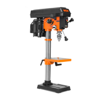
Fig. Q
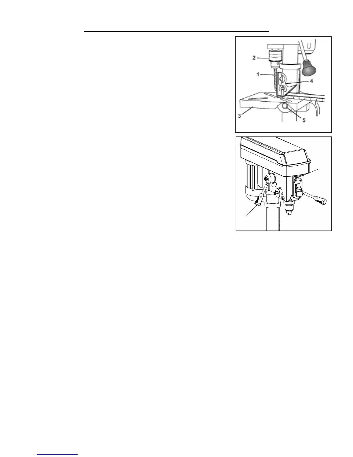
Fig. R
2
1
1. Insert a 3-inch-long drill bit (Fig. Q - 1) into the chuck (Fig. Q - 2) and tighten.
2. Raise and lock the table (Fig. Q - 3) about 1” from the end of the drill bit.
3. Place a combination square (Fig. Q - 4) on the table as shown. The drill bit should be parallel to the straight
edge of the square.
4. If an adjustment is needed, loosen the bevel lock (Fig. Q - 5) with a wrench. Square the table to the bit by tilting
the table. Tighten the bevel lock bolt (Fig. Q - 5) when square.
VARIABLE SPEED ADJUSTMENT
This is a mechanical variable speed drill press. To increase or decrease the speed, raise or lower the speed adjust-
ing handle (Fig. R - 1) while the drill press is running. When drilling, check the speed on the digital speed display
on the front of the drill press (Fig. R - 2).
NOTE: Do not attempt to change the drill press speed while the drill press is off. This can damage the drill press
and void the warranty.
 Loading...