ASSEMBLY & ADJUSTMENTS
ASSEMBLY & ADJUSTMENTS
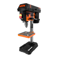
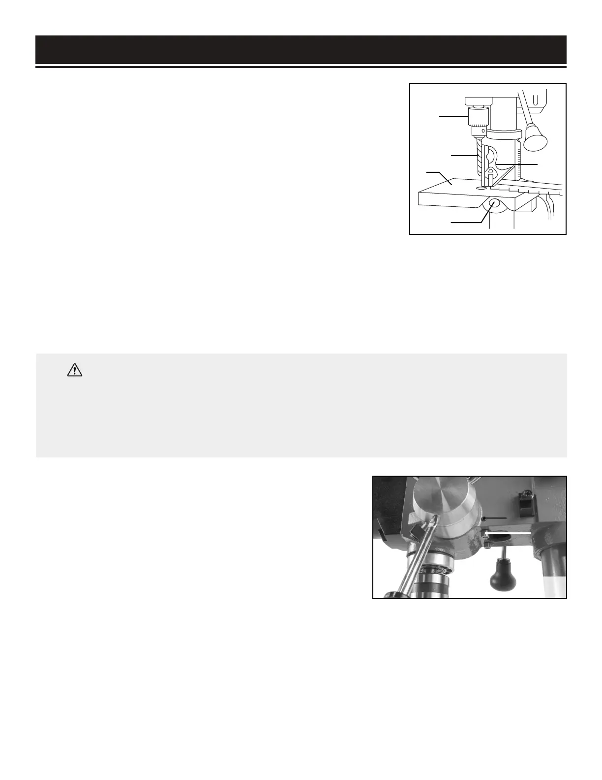
SQUARING THE TABLE TO THE DRILL BIT (FIG. 14)
1. Insert a 3" drill bit (Fig. 14-1) into the chuck (Fig. 14-2) and
tighten.
2. Raise and lock the table (Fig. 14 - 3) about 1" from the end of the
drill bit.
3. Place a combination square (Fig. 14 - 4) on the table as shown.
The drill bit should be parallel to the straight edge of the square.
4. If an adjustment is needed, loosen the bevel lock (Fig. 14 - 5) with
a wrench.
5. Square the table to the bit by tilting the table.
6. Tighten the bevel lock bolt (Fig. 14 - 5) when square.
1
2
3
4
5
ADJUSTING THE LASER (FIG. 15)
1. Place a workpiece on the table.
2. Turn the laser switch to the ON position.
3. Lower the drill bit to meet the workpiece. The two laser lines
should cross where the drill meets the workpiece.
15
1
2
WARNING: Do not stare directly at the laser beam. Observe all safety rules.
• Never aim the beam at a person or an object other than the workpiece.
• Always make sure the laser beam is aimed at a workpiece that does not have reflective surfaces, as
the laser beam could reflect into your eyes or the eyes of others.
Fig. 14
Fig. 15
4. If the laser needs to be adjusted:
a) Using a 3 mm hex key, turn the laser adjustment screws (Fig. 15 - 1) counterclockwise.
b) Rotate the laser light housing (Fig. 15 - 2) until the two laser lines intersect where the drill meets
the workpiece. DO NOT stare directly at the laser lines.
5. Re-tighten the adjustment set screws (Fig. 15 - 1).
 Loading...