16
ASSEMBLY & ADJUSTMENTS
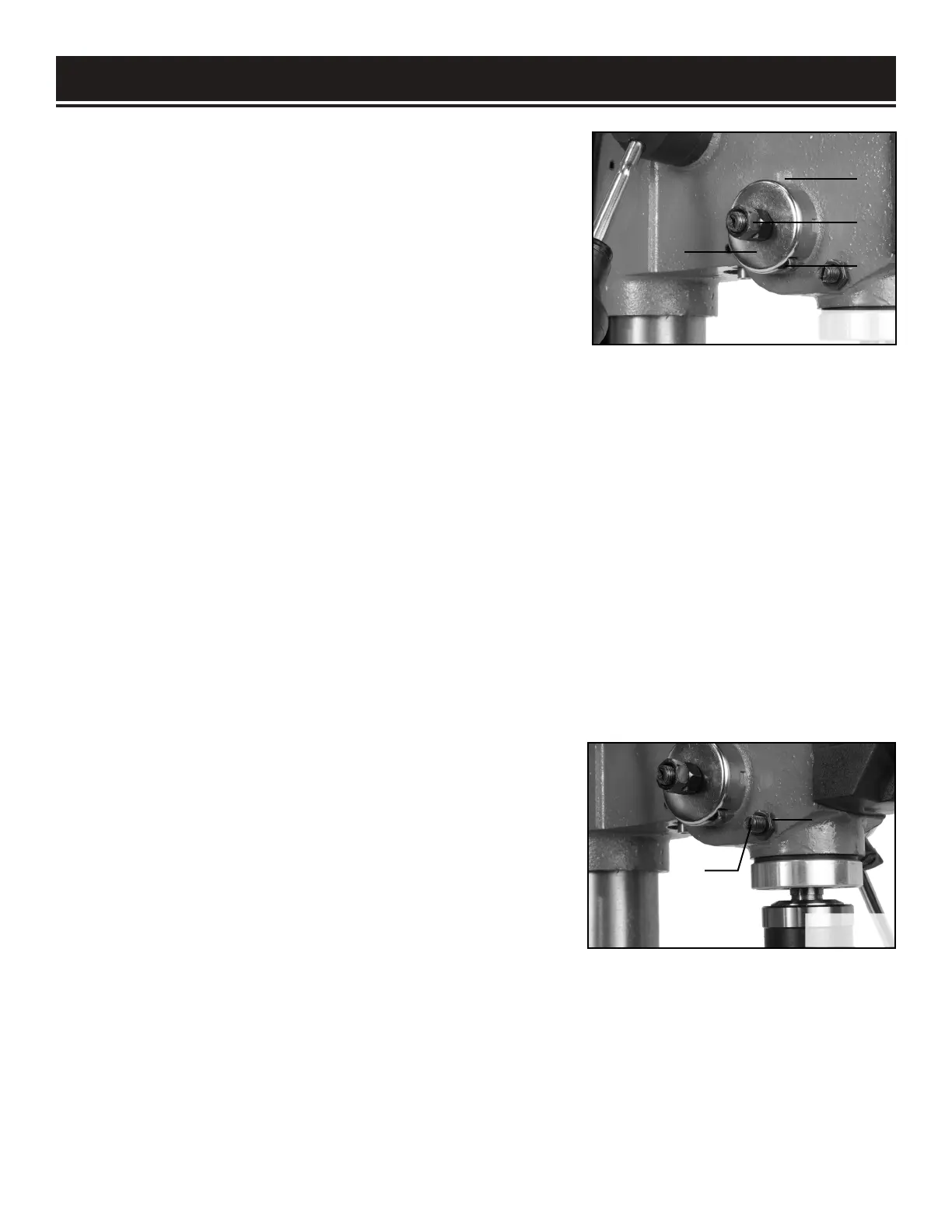
SPINDLE RETURN SPRING (FIG. 16A)
The spindle is equipped with an auto-return mechanism. The
main components are a spring and a notched housing. The
spring was properly adjusted at the factory and should not be
readjusted unless absolutely necessary.
1. Unplug the drill press.
2. Place a screwdriver into the loop (Fig. 16A - 1) to hold the
spring in place.
ASSEMBLY & ADJUSTMENTS
1
2
3
4
5
6
3. Loosen the two housing nuts (Fig. 16A - 3) approximately 1/4" (6 mm). Do not remove the nuts from the
threaded shaft. Do not allow the spring or spring housing to slip out of control.
4. While firmly holding the spring housing (Fig. 16A - 4), carefully pull the spring housing out until it clears
the raised notch (Fig. 16A - 2).
5. Turn the housing so that the next notch is engaged with the raised notch (Fig. 16A - 2).
• To increase the spindle return tension, turn the spring housing counter-clockwise.
• To decrease the tension, turn the spring housing clockwise.
6. Tighten the two housing nuts. Do not overtighten the two nuts. If the nuts are tightened too much, the
movement of the spindle and feed handles will become sluggish.
ANGULAR “PLAY” OF THE SPINDLE (FIG. 16B)
Move the spindle to the lowest downward position and hold
in place. Try to make the spindle revolve around its axis while
also moving it with a side motion. If there is too much “play”,
proceed as follows:
1. Loosen the lock nut (Fig. 16B - 5).
2. Without obstructing the upward and downward motion of
the spindle, turn the screw (Fig. 16B - 6) clockwise to eliminate
the “play.” NOTE: A little bit of “play” is normal.
3. Tighten the lock nut (Fig. 16B - 5).
Fig. 16A
Fig. 16B
 Loading...