9
ASSEMBLY
WARNING: To avoid injury from unexpected starting or electrical shock, do not plug the power cord into a
source of power during unpacking and assembly. This cord must remain unplugged whenever you are adjusting/
assembling the grinder. If any part is missing or damaged, do not attempt to assemble the grinder or plug in the
power cord. All of the parts needed for assembly should be located and accounted for before beginning.
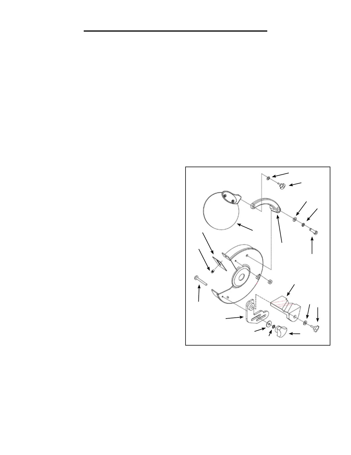
TOOL REST ASSEMBLY
1. Place the tool rest (C) over the tool rest support (G) and secure in position with a 6mm flat washer (B) and
knob (A).
2. Attach the tool rest support to the bottom of the left wheel guard. Insert a carriage bolt (P) through cover and
guard. Place upper slot of support over carriage bolt and lower slot over the raised boss on guard. Secure support
using 5mm flat washer (F), 5mm lock washer (E) and knob (D). Tighten knob finger tight.
3. Position tool rest so that distance between tool rest and grinding wheel is 1/16” or less. Reposition angle of tool
rest if necessary. Secure all knobs.
Fig. B
4. Mount right tool rest in a similar manner.
SPARK DEFLECTOR AND EYE SHIELD
ASSEMBLY
1. Attach spark deflector (N) to left wheel guard using
5mm flat washer, 5mm lock washer and pan head screw
(O). Make sure spark deflector is ¼” or less away from
grinding wheel.
2. Attach eye shield support (L) to left wheel guard using
6mm flat washer (B), 6mm lock washer (I) and hex head
bolt (H).
3. Attach eye shield (M) to eye shield support using
5mm flat washer (K) and knob (J).
4. Position eye shield as desired and secure all knobs
and bolts.
5. Attach spark deflector and eye shield assembly to
right wheel guard in a similar manner.
M
O
N
P
G
F
E
D
C
B
A
H
L
I
B
J
K