88
ASSEMBLY AND ADJUSTMENTS
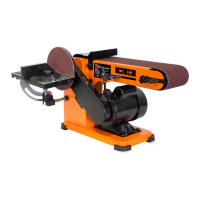
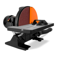
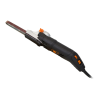
FEET INSTALLATION (Fig. B)
1. Carefully set the belt sander on its side.
2. Find the four rubber feet (Fig. B - 1) in the parts bag.
3. Press-fit each rubber foot over the lip of the corners around the
base of the machine.
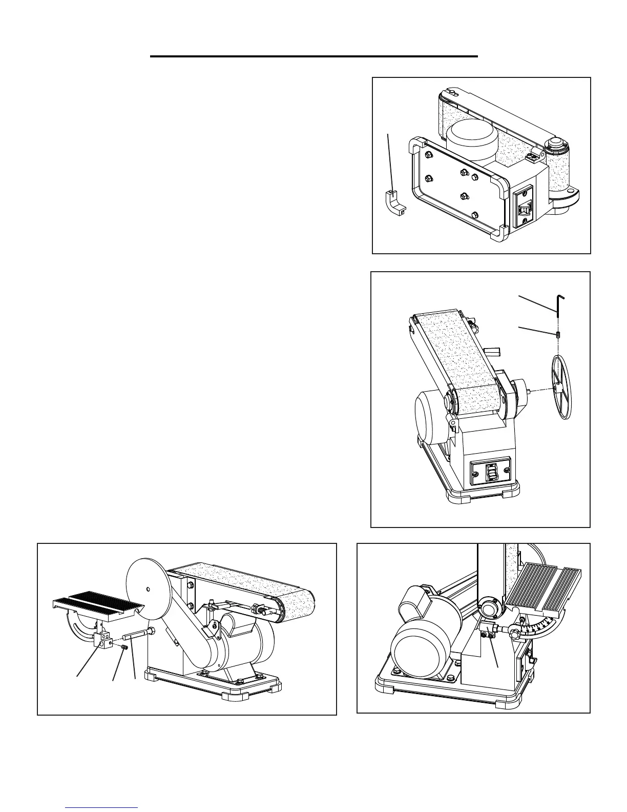
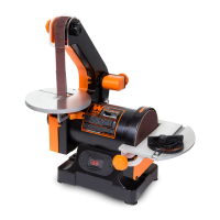
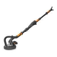
MOUNT THE DISC SANDER TABLE
1. Install the support rod with nut (Fig. D - 2) into the hole on the
body below the sander’s disc. Make sure the flat surface of the rod
is oriented in the vertical position and is securely tightened to the
nut.
2. Slide the pivot bracket (Fig. D - 3) all the way onto the rod and
tighten the set screw.
3. The table can also be installed to the support block (Fig. E - 1)
beside the body for the vertical belt sanding operation.
MOUNTING THE ALUMINUM DISC (Fig. C)
1. Place the belt sander so that it is sitting on its feet.
2. Loosen the disc’s set screw (Fig. C - 2) with a hex wrench (Fig.
C - 1).
3. Slide the disc all the way onto the drive shaft so that the set screw
faces the shaft’s flat surface.
4. Securely tighten the set screw.
1
2
1
Fig. B
Fig. C
Fig. D
Fig. E
3
2
1
1