ASSEMBLY & ADJUSTMENTS
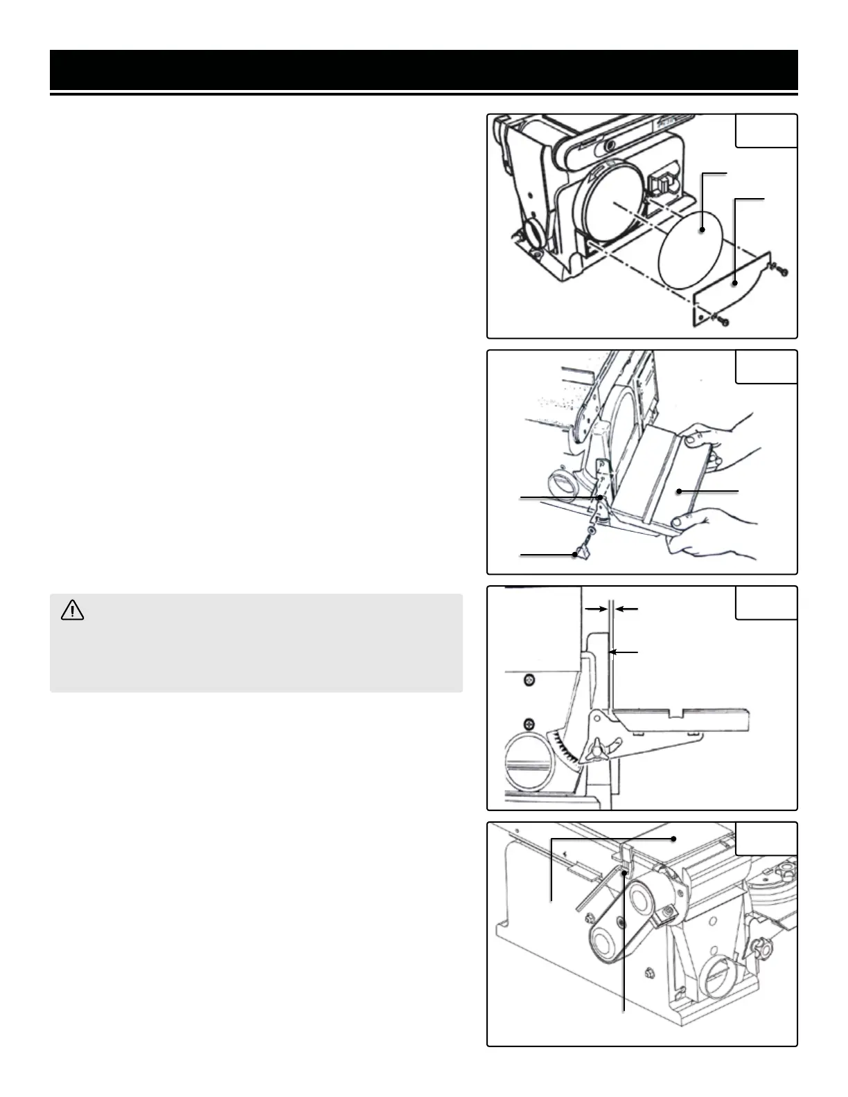
INSTALLATION OF SANDING DISC & GUARD
1. Peel backing away from sanding disc (Fig. 2 - 1).
2. Align perimeter of disc with plate, and press disc firmly into
position on plate, leaving no loose edges.
3. Position disc guard (Fig. 2 - 2) against lower 1/3 of disc,
aligning holes as shown. Use a screwdriver to fasten the pro-
vided screws and washers securely.
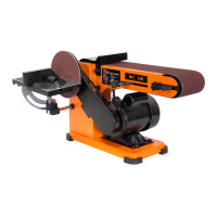
MOUNT THE DISC SANDER TABLE
1. With the table (Fig. 3 - 1) in a horizontal position, line up and
insert the pivot indexing pin (Fig. 3 - 2) with the pivot hole on
the frame. Hold in place.
2. Insert the table lock knob (Fig. 3 - 3) into the threaded hole
and tighten.
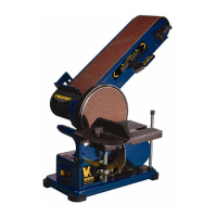
3. Adjust the table so that the edge is a maximum of 1/16 inch
from the disc. (Fig. 4)
NOTE: If needed, make minor adjustments to the position of the
table by loosening the three bolts that appear on the underside
of the table. Once the desired clearance is achieve, retighten
these three bolts.
WARNING! To avoid trapping the workpiece or fingers
between the table and the sanding disc, the table edge should
be adjusted to a maximum of 1/16 inch from the sanding
disc.
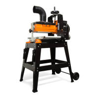
MOUNTING THE WORK SUPPORT
1. Align the work support (Fig. 5 - 1) with the hole.
2. Install a lock washer and a flat washer on the hex screw.
3. Insert the hex screw into the work support hole and tighten
(Fig. 5 - 2).
4. Adjust the work support height to avoid contact with the
sanding belt.
1
Fig. 2
2
Fig. 3
3
2
1
Fig. 4
1/16" Max
Sanding Surface
Fig. 5
1
2
10