ASSEMBLY & ADJUSTMENTS
WARNING: Do not plug in or turn on the tool until it is fully assembled according to the instruc-
tions. Failure to follow the safety instructions may result in serious personal injury.
ACCESSORY SELECTION
Refer to the packing list diagram on page 10 to ensure that you are using the proper sizes of throat plates,
drums and washers for each respective sanding sleeve. To ensure the workpiece can be properly supported
and to minimize clearance, use the throat plate that matches the drum and sleeve that you’ll be working with.
The size of the throat plate is marked on the plate's surface.
NOTE: The smallest size sanding sleeve does not include a drum. It goes directly onto the bare spindle.
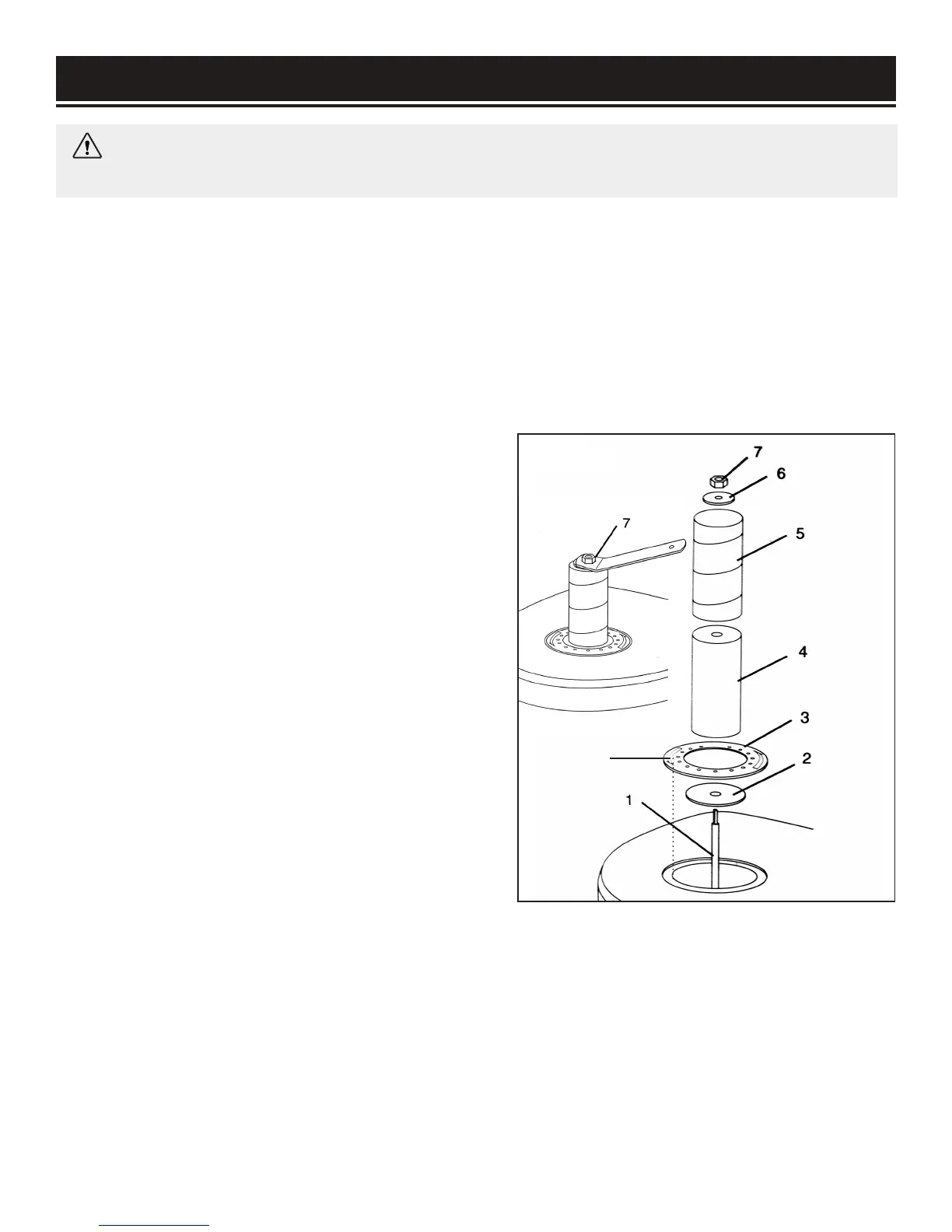
INSTALLING THE ACCESSORIES
1. Disconnect the machine from the power source.
2. Slide the lower spindle washer (Fig. 2 - 2) over the
spindle shaft.
3. Install the preferred rubber drum (Fig. 2 - 4) onto the
spindle shaft, followed by the corresponding sanding
sleeve (Fig. 2 - 5) and throat plate (Fig. 2 - 3). Make
sure the printed side of the throat plate is facing up.
NOTE: The 1/2" sleeve will be installed directly onto the
spindle.
4. Secure the sanding accessories in place with the cor-
responding washer (Fig. 2 - 6). Tighten the spindle nut
on top (Fig. 2 - 7) with the spindle nut wrench until the
sanding drum is fully expanded and securely holds the
sanding sleeve. The sleeve should not be able to freely
rotate without also rotating the sanding drum.
Fig. 1
Align the
notch
11

 Loading...