ASSEMBLY & ADJUSTMENTS
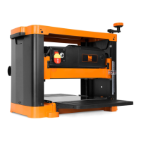
ATTACHING THE DEPTH ADJUSTMENT HANDLE
1. Secure the depth adjustment handle (Fig. 2 - 1) to the top of the planer
using the included socket head bolt (Fig. 2 - 2) and washer (Fig. 2 - 3).
3. Place the handle cap (Fig. 2 - 4) on top of the depth adjustment handle,
covering the socket head bolt and washer.
NOTE: With each full rotation of the depth-adjustment handle, the plan-
er’s height adjusts 1/16”. For example, 1/4 of a rotation is 1/64”, 1/2 of a
rotation is 1/32”, and 1 full rotation is 1/16”.
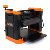
PREPARING THE TABLES
1. Lower the infeed and outfeed tables (Fig. 3).
Remove the foam insert located between the main table and the cutter-
head.
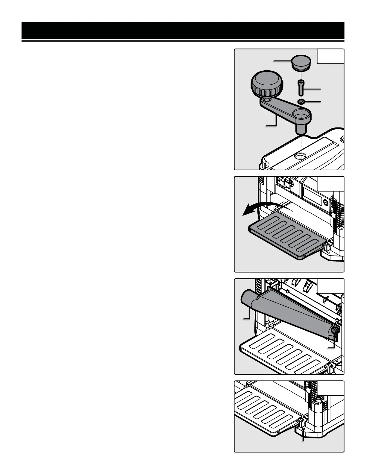
ATTACHING THE DUST CHUTE
1. Mount the dust chute (Fig. 4 - 1) to the rollercase using the two thumb
screws (Fig. 4 - 2).
NOTE: The dust chute can be mounted in either direction to direct the
flow of chips to either side of the planer.
2. After mounting, connect a dust collection system to the dust chute. Be
sure to turn the vacuum system on before operating the planer.
NOTE: If you do not plan on using a dust collection system of any kind,
we recommend removing the dust chute so that the wood chips and
debris can fly freely from the back of the planer. This will, however, make
a mess in your shop. The other option would be to leave it on and then
regularly clean the wood shavings and dust out of the planer and chute
during operation. Any damage or other problem caused by a failure to
keep the planer clean (by not using dust collection, removing wood
chips, etc.) is not covered under the warranty.
MOUNTING THE PLANER TO A WORK SURFACE
The planer should always be mounted to a stable, level bench or table in a
well-lit area. Make sure there is plenty of room for moving the workpiece
through the entire cut. Neither the operator nor bystanders should stand
in line with the workpiece while the tool is operating.
1. Mount the planer to a workbench or tool stand using four bolts, four
flat washers, and four hex nuts (not included) through the mounting
holes on the base (Fig. 5).
Fig. 2
Fig. 3
Fig. 4
1
2
3
4
1
2
Fig. 5
Mounting Holes
10
 Loading...