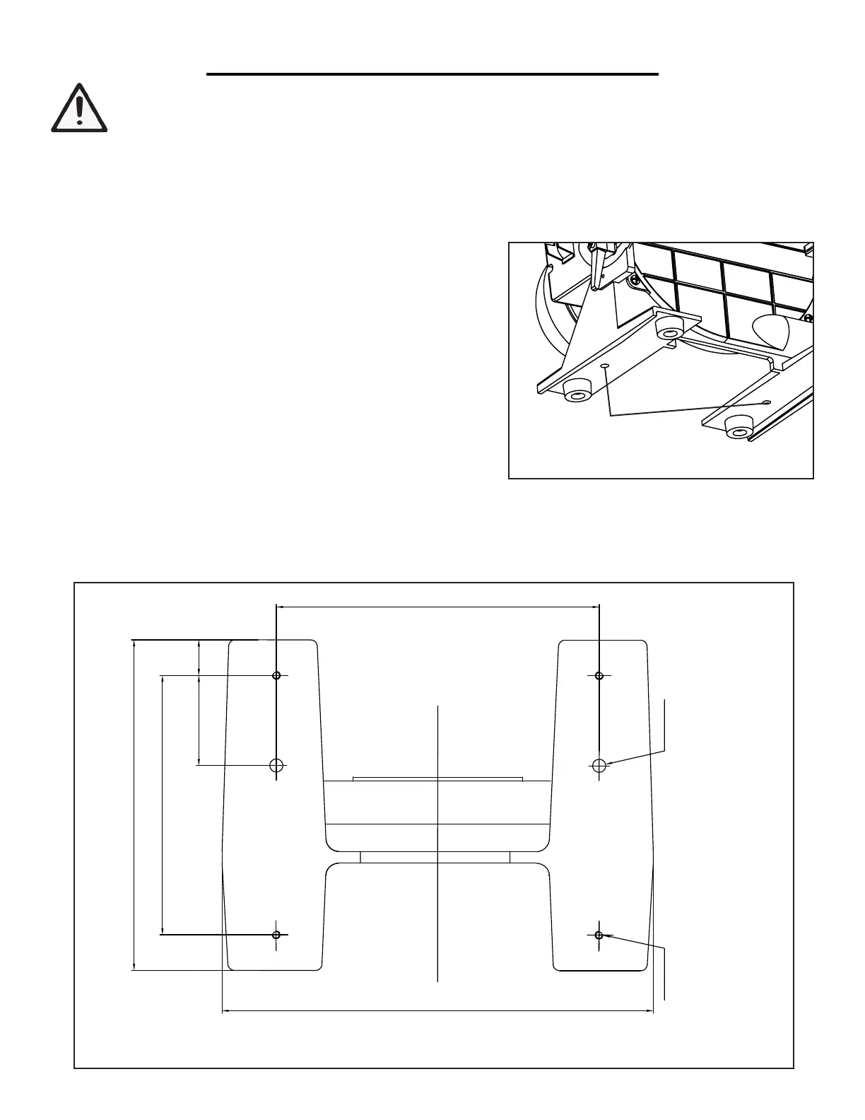
248mm
25mm60mm
200mm
250mm
328mm
FRONT
Mouting Hole
2xø10mm
Rubber Feet Hole
4xM6
WARNING: To prevent serious injury from accidental operation, make sure the power cord is discon-
nected from the power source and the tool is turned OFF before assembly or making any adjustments.
ASSEMBLY & ADJUSTMENTS
SECURING SANDER TO A WORKBENCH
For safe operation, the machine must be secured onto a flat, secure workbench or stand. Refer to the base dimen-
tsions shown in Fig. 2. For temporary mounting, attach a large C-Clamp to each side of the sander and the work-
bench. For permanent mounting, follow the instructions below:
1. Place the sander on a stable workbench.
2. A mounting hole is located on each leg towards the rear of the
sander body (Fig. 1). Insert a pencil through the two mounting
holes and mark the hole locations on the workbench.
3. Remove sander. Drill two 3/8" holes through the workbench.
4. Align the sander base over the mounting holes and secure it
using two 5/16" screws and washers, locking washers and hex nuts
(mounting hardware not included).
Mounting
holes
Fig. 1
Fig. 2
NOTE: Your sander is compatible with the WEN 6588 Multipurpose Planer Stand, available at wenproducts.
com. Forget measuring and drilling holes on your workbench, simply mount your machine onto the mobile
stand with pre-drilled holes, and transport your machine around the workshop with ease.
9