11
ASSEMBLY & ADJUSTMENTS
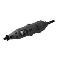
ATTACH THE FENCE
1. Attach the fence support bracket (Fig. 2 - 1) to the jointer with
four socket head bolts (Fig. 2 - 2)
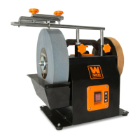
2. Assemble the fence sliding bracket (Fig. 3 - 1) to the fence
(Fig. 3 - 2). Insert the two socket head bolts (Fig. 3 - 3) through
the top of the fence sliding bracket and screw the square nuts
(Fig. 3 - 4) onto the bolts but do not tighten.
3. Slide the square nuts into the grooves on the back of the
fence and position the fence sliding bracket to the middle of the
fence. Tighten the socket head screws (Fig. 3 - 3) once the slid-
ing fence bracket is correctly positioned.
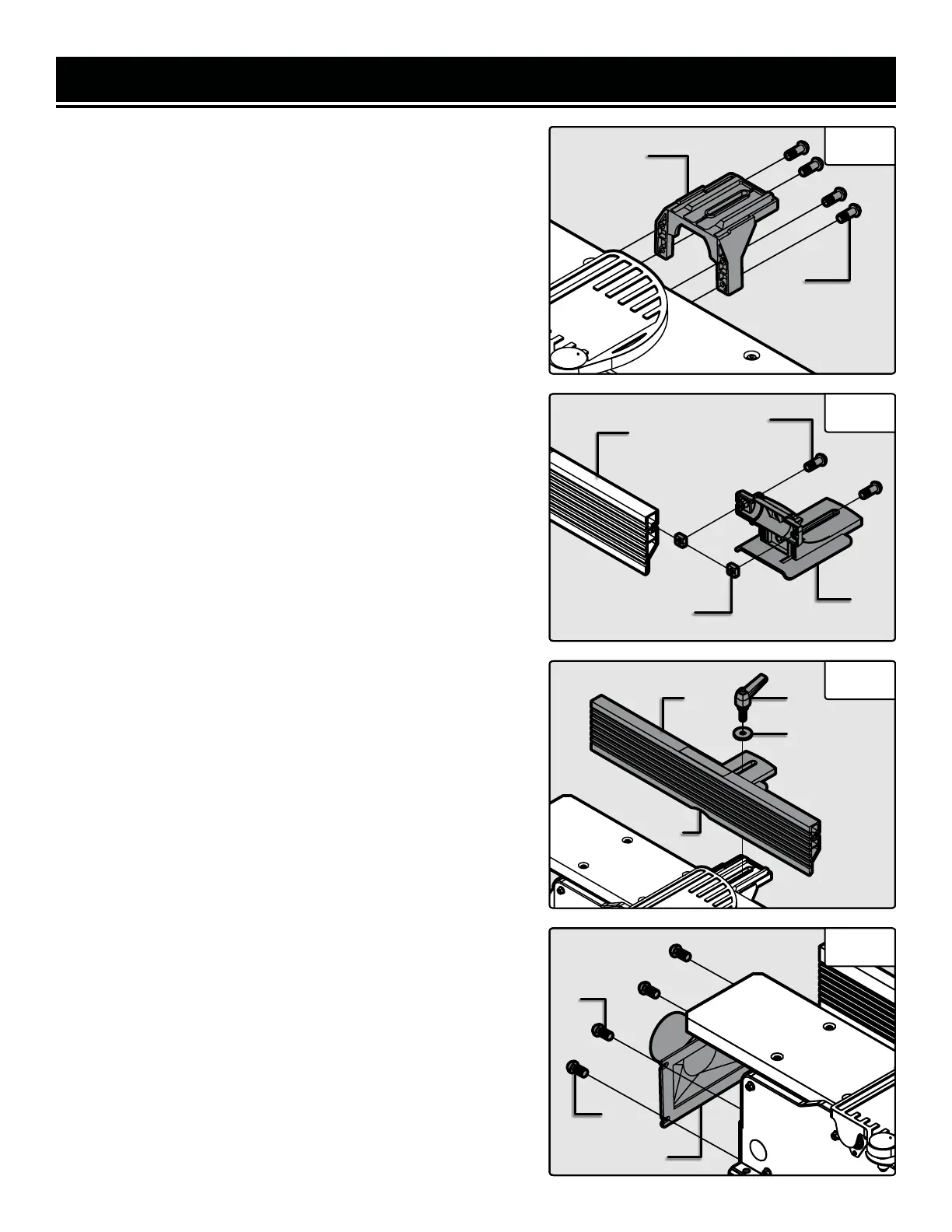
NOTE: Use the fence cutout (Fig 4 - 1) to position the fence slid-
ing bracket in the center of the fence.
4. Place the upper fence assembly (Fig. 4 - 2) on top of the fence
support bracket. Insert the sliding handle (Fig. 4 - 3) through
the flat washer (Fig. 4 - 4), through the sliding bracket, and then
though the support bracket.
5. Hold the rectangular nut under the fence support bracket so
that it fits snuggly into the groove with the flat side up. Thread
the sliding handle through the nut until it is tight. and the fence
is secured.
NOTE: The fence sliding handle and fence bevel handle are
spring-loaded and can be re-positioned as need be. Pull out on
the handle, re-position it, and let it spring back in place.
NOTE: The stop limits on the fence bracket have been set at the
factory, but should be checked with an angle gauge to measure
exactly 90° and 135° between the fence and the table top at each
stop limit, respectively. The stop limits can be modified by tight-
ening or loosening the set screws if the angles are not precise.
INSTALL THE DUST CHUTE
1. Remove the two M6x12 screws (Fig. 5 - 1) from the body of
the jointer and the two self tapping screws (Fig. 5 - 2) from the
feet of the jointer.
2. Position the dust port (Fig. 5 - 3) and reinstall all four screws.
Be sure not to over-tighten the screws as doing so might dam-
age the dust port.
NOTE: JT833H comes with an optional dust port adapter to al-
low you to connect to 2-1/2” or 4” hoses.
Fig. 2
1
2
Fig. 3
1
2
3
4
Fig. 4
Fig. 5
1
2 3
4
1
2
3

 Loading...