Seite 13 von 18 WH-1, WH-2, WH-3, WH-4
7 Function
7.1 Basis pump
All WH-1 – WH-4 series hand pumps have the two-stage design, i. e. they are working with two different speeds:
a high speed in the low-pressure range (LP) for fast extension of a cylinder without load and a low speed in the high-pressure range
(HP) for controlled extension of a cylinder with a load resting on it.
Switch-over from low to high pressure mode is done automatically by a factory-preset switch-over valve (see also technical data).
7.2 Upgrade kits
The standard pump WH-2 – WH-4 can be upgraded with additional functions using the following connecting plates
Each upgrade kit (except pressure gauge connector) is delivered with fixing (22Nm) and sealing material.
8 Putting into Operation
8.1 Preparing the pump
The pump is, normally, connected to a hydraulic cylinder by means of suitable pressure hoses
or, for Stationary applications via pipes. The hose connection nipple is to be mounted at
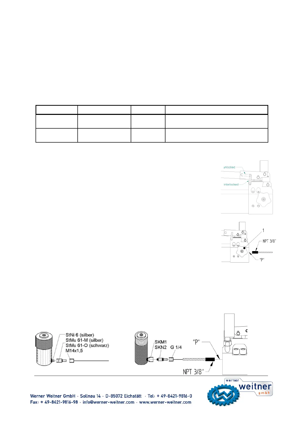
outlet „P“(2) on the pump head and to be tightened with a torque of 35 +5 Nm.
For using the pump you have to extract the locking (4) out of the drilling, which is positioned
in the pumphead, and turn it on 90° in a clockwise direction to unlock the pumplever (6).
The locking (4) has to snap in the drilling of the pumhead.To lock the pump, you have to think
gradually backward. At first you take the locking (4), extract it out of the drilling in the pumplever (6),
turn it on 90° contraclockwise and lock it in the drilling in the pumphead. The pumplever (6) acts as
a grasp for carrying.At first use of hanpump WH-1 in high pressure zone, it is possible that a little
no-load stroke results. This no-load stroke adjusts itself after joining a cylinder, who was extended 2 - 3 times.
8.2 Venting the pump
Check the oil level (approx. 1-2 cm below upper edge of the oil container, depending
on the container size, ref. to section 16)
• Open drain valve (1)
• Actuate the pump several times.
8.3 Venting the cylinder
Connect the cylinder with the pump. Extend the piston by half its stroke and turn the cylinder so that the piston is facing downwards.
The highest point of the cylinder must be on a lower level than the pump. Fully extend the piston and retract again so that eventual
air bubbles can escape into the oil container of the pump.
Remark:
The oil filler cap of the pump must be open during bleeding. While retracting the piston air bubbles will be pushed via the hydraulic
hose into the oil reservoir and can escape through the filler cap.
9 Operation of two single-acting cylinders and rescue devices
9.1 Connection of a single-acting hydraulic cylinder
system 50 MPa system 70 MPa
Upgrade kit Order - no. Weight (kg) Function or application
4/3 - way - valve ww-WV-4/3 1 Control valve für extension and retraction of
double acting cylinders.
Connecting plate WW-AP700/3210/DH 0,4 1x Connection P - G 1/4"
1x Tank runback T - G 1/4"
 Loading...