Seite 14 von 18 WH-1, WH-2, WH-3, WH-4
9.1.1 Operation of a single-acting cylinder
- fully close the hand wheel (1) on the pump head (turn it clockwise)
- extend the cylinder by operating the hand lever of the pump. Observe safety remarks as per para 10.1!
9.1.2 Connecting a single acting rescue device
The unit is connected to the pressure hose line marked in red. If present, the return hose line marked in blue has no function.
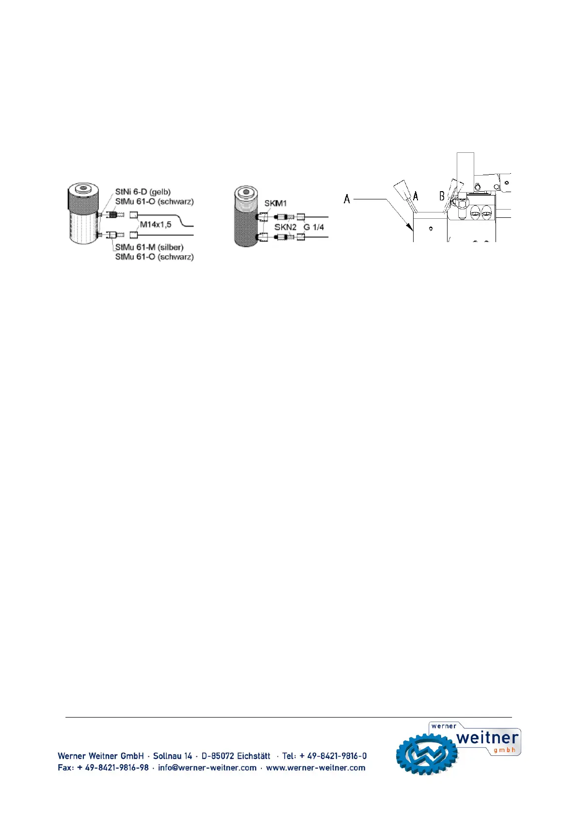
9.2 Connection of a double-acting cylinder
system 50 MPa system 70 MPa
9.2.1 Connection of a double-acting cylinder
- Mount upgrade kit N4/3W (4/3-way valve) at the connecting plate as per
separate mounting instruction (comes with the valve kit).
- fix the hand pump in vertical position to prevent oil spill and remove
locking screws from outlets A and B on N4/3W valve kit.
- mount hydraulic hoses at outlets A and B and tighten them with a torque of
45 +5 Nm.
- mount couplers as per para 8.2
Safety advise:
Within the 50 MPa quick coupling system at least one hydraulic hose must be equipped with the quick-connect socket StMu61-O
(colour black). This hose must always be connected to the return connector on the head area of the cylinder (see picture above). By
no means the return connection must be coupled with a quick-connect socket StMu 61-M (colour silver), as this combination
could cause a pressure boosting beyond the permissible pressure.
9.2.2 Operation of a double-acting cylinder
- fully close the hand wheel (1) by turning it clockwise
- switch the hand lever on the 4/3-way valve to position A or B
(extension or retraction).
- activate the cylinder by operating the pump lever(6). Observe safety
remarks as per para 10.1!
9.2.3 Load holding function
The 4/2-way valve (N4/2W) itself does not have such a function.
Load can be sustained when the hand wheel (1) is fully closed. The lever of the N4/2W valve must thereby stay in position
„extending“.
9.3 Connection of rescue device
9.3.1 Connecting a double acting rescue device
The device is connected to the
connecting hoses (refer to item 8.1)
via coupling counterparts (plug and socket) that cannot
be connected in the wrong way.
Plug and socket – refer to item 9.6.
9.3.2 Actuating the rescue device
The pump is prepared for the subsequent work steps by turning the relief wheel at the relief valve to the right (closed = pressurized)
(Close relief valve of the pump by hand only. The use of tools, pincers in particular, may damage the valve seat) and by turning the
locking cap at the oil-filler neck (3) (in order to let the air out of the oil container).
The relief valve of the hand pump is normally kept closed. It must only be opened if the high-pressure hose cannot be coupled
because pressure has developed as a result of faulty operation or heat.
Hold the control valve of the rescue device in the desired direction of movement and actuate the pump lever.
Note: Carry out short strokes to save your strength when pumping under high pressure. The maximum pumping force is achieved
during the final five degrees of the stroke.