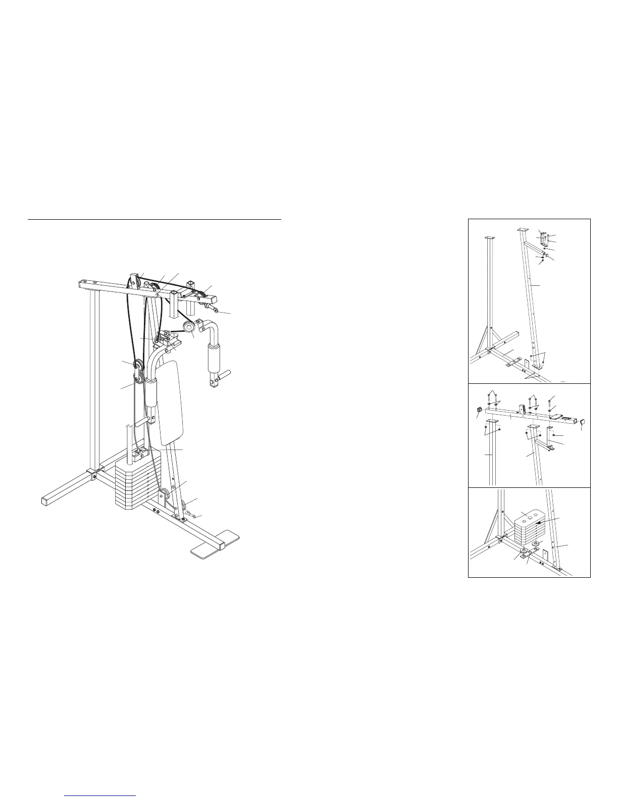
5
3. Press the 1 1/4Ó Inner Cap (57) into the Front Upright
(42).
Attach the 1Ó Plastic Stop (64) to the centre hole in
the Stop Bracket (63) with a 5/16Ó x 1 1/2Ó Bolt (24)
and a 5/16Ó Jam Nut (2).
Attach the Stop Bracket (63) to the Front Upright (42)
with the 5/16Ó x 2Ó Bolt (61), a 5/16Ó Flat Washer (8)
and a 5/16Ó Nylon Lock Nut (3).
Slide the Front Upright (42) onto the two 5/16Ó x
2 1/2Ó Carriage Bolts (1) in the Base (4). Attach the
Front Upright to the Base with two 5/16Ó Nylon Lock
Nuts (3). Do not tighten the Nylon Lock Nuts yet.
4. Press two 2Ó Inner Caps (27) into the Top Frame (67).
Attach the Top Frame (67) to the Front Upright (42)
with two 5/16Ó x 2 3/4Ó Bolts (11), two 5/16Ó Flat
Washers (8) and two 5/16Ó Nylon Lock Nuts (3). Do
not tighten the Nylon Lock Nuts yet.
Attach the Top Frame (67) to the Stop Bracket (63)
with a 5/16Ó x 2 3/4Ó Bolt (11), a 5/16Ó Flat Washer (8)
and a 5/16Ó Nylon Lock Nut (3). Do not tighten the
Nylon Lock Nut yet.
Attach the Top Frame (67) to the Rear Upright (82)
with two 5/16Ó x 2 3/4Ó Bolts (11), two 5/16Ó Flat
Washers (8) and two 5/16Ó Nylon Lock Nuts (3).
Tighten all Nuts used in steps 2 through 4.
5. Set the two Weight Bumpers (19) on the indicated
plate on the Base (4). Align the holes in the Weight
Bumpers with the holes in the plate.
Stack seven Weights (25) on the Weight Bumpers
(19). Each Weight must be turned so the pin groove
is facing the Front Upright (42). The holes in the
Weights must be aligned with the holes in the Weight
Bumpers. CAUTION: Be careful to avoid tipping
the stack of Weights until step 6 is completed.
3
4
5
3
57
42
64
63
24
2
61
8
3
1
4
27
27
67
42
11
8
3
11
8
3
63
11
82
8
3
19
19
4
25
42
Pin Groove