156
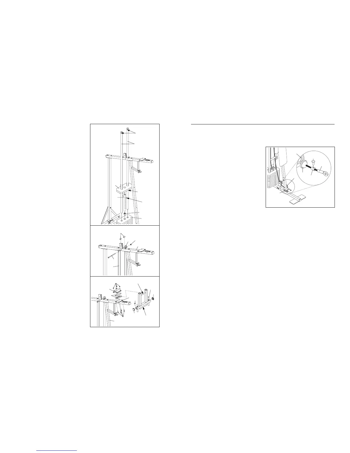
6. Press the Weight Tube Bumper (79) into the
lower end of the Weight Tube (80).
Insert the Weight Tube (80) into the stack of
Weights (25). Slide the eighth Weight onto the
upper end of the Weight Tube. The Weight Tube
must be turned so the welded pin is in the pin
groove in the Weight.
Locate the lower ends of the Weight Guides
(72)Ñthere are holes near the upper ends. Insert
the lower ends of the Weight Guides into the
eight Weights (25).
7. Attach the upper ends of the Weight Guides (72)
to the Top Frame (67) with the 5/16Ó x 6Ó Bolt
(74), the two Weight Guide Spacers (73) and a
5/16Ó Nylon Lock Nut (3).
8. Press two 1 3/4Ó Inner Caps (44) and two 1Ó
Round Inner Caps (49) into the Arm Frame (52).
Apply lubricant to the upper axle on the Arm
Frame (52). Hold the axle between the two Arm
Frame Bushings (68). Set the Arm Frame
Bushings and the Arm Frame on the plate welded
to the top of the Top Frame (67). The Arm Frame
must be turned so the bracket is facing away
from the Front Upright (42). Place the Arm Frame
Bracket (69) over the Arm Frame Bushings.
Attach the Arm Frame Bracket to the Top Frame
with four 1/4Ó x 3/4Ó Screws (18) and four 1/4Ó
Nylon Lock Nuts (7).
6
7
8
TROUBLE-SHOOTING AND MAINTENANCE
Inspect and tighten all parts each time you use the weight system. Replace any worn parts immediately. The
weight system can be cleaned using a damp cloth and mild non-abrasive detergent. Do not use solvents.
TIGHTENING THE CABLES
Woven cable, the type of cable used on the weight
system, can stretch slightly when it is first used. If
there is slack in the cables before resistance is felt,
the cables should be tightened. Locate the adjustment
sleeve and adjustment screw near the lower end of
the Short Cable (23). Loosen the adjustment screw.
Pull the end of the Short Cable until there is no slack.
Slide the adjustment sleeve and the ball against the
indicated 3 1/2Ó Pulley (15). Retighten the adjustment
screw. Make sure that the cables are not too tight, or
the top weight will be lifted off the weight stack.
23
15
15
Adjustment
Screw
Adjustment
Sleeve
Ball
23
79
Pin
Groove
Welded
Tube
80
72
Upper Ends of
Weight Guides
have Holes
25
25
72
72
67
74
73
3
44
Bracket
68
67
49
49
42
69
18
7
44
52ÑLubricate