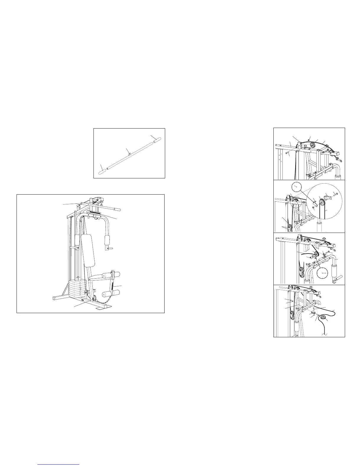
16. Insert the end of the Long Cable (66) through the
indicated bracket on the Top Frame (67), and
down through the indicated hole in the Top
Frame.
Hold a 3 1/2Ó Pulley (15) inside the bracket on the
Top Frame (67). The Long Cable (66) must be
between the Pulley and the top of the bracket.
Attach the Pulley to the bracket with a 3/8Ó x 1
3/4Ó Bolt (12) and 3/8Ó Jam Nut (6).
17. Insert the Long Cable (66) between the ÒIÓ Plates
(78).
Lay the Long Cable (66) over a 3 1/2Ó Pulley (15)
(see the inset drawing). Attach the Pulley and a
Cable Trap (59) to the Wide Swivel Bracket (71)
with a 3/8Ó x 1 3/4Ó Bolt (12) and 3/8Ó Jam Nut (6).
The Cable Trap must be turned to the Ò10 oÕclockÓ
position.
18. Wrap the Long Cable (66) down around a 3 1/2Ó
Pulley (15). Attach the Pulley and a Cable Trap
(59) to the Narrow Swivel Bracket (58) on the left
Arm (46) with a 3/8Ó x 1 3/4Ó Bolt (12) and 3/8Ó
Jam Nut (6). The Cable Trap must be turned to
the Ò3 oÕclockÓ position.
19. Attach the Adjustment ÒUÓ Bracket (75) to the
Front Upright (42) with a 5/16Ó x 3Ó Bolt (17), a
5/16Ó Flat Washer (8) and a 5/16Ó Nylon Lock Nut
(3). Note: This Bracket is used to adjust the
tension of the Long Cable. Thread the Nylon
Lock Nut onto the Bolt only two complete
turns.
Wrap the Long Cable (66) around a 4 1/2Ó Pulley
(77). Attach the Pulley to the Adjustment ÒUÓ
Bracket (75) with a 3/8Ó x 1 3/4Ó Bolt (12) and 3/8Ó
Jam Nut (6).
16
18
17
19
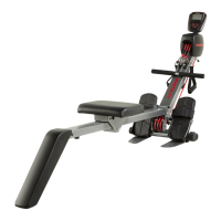
27. Wet the ends of the Lat Bar (85) and insides of the
two remaining Handgrips (48) with soapy water.
Slide the Handgrips onto the ends of the Lat Bar.
27
85
48
48
29. Make sure that all parts are properly tightened. The use of all remaining parts will be explained in ADJUST-
MENT, beginning on page 13 of this user's manual. Before using the weight system, pull each cable a few
times to make sure that the cables move smoothly over the pulleys. If one of the cables does not move
smoothly, locate and correct the problem before using the weight system. IMPORTANT: If the cables are
not properly routed, they may be damaged when heavy weight is used. See the CABLE DIAGRAM on
page 16 of this userÕs manual.
28. Remove the decals from the Decal Sheet (not shown), and apply them to the weight system in the locations
shown in the drawing below.