8
General Technical Description
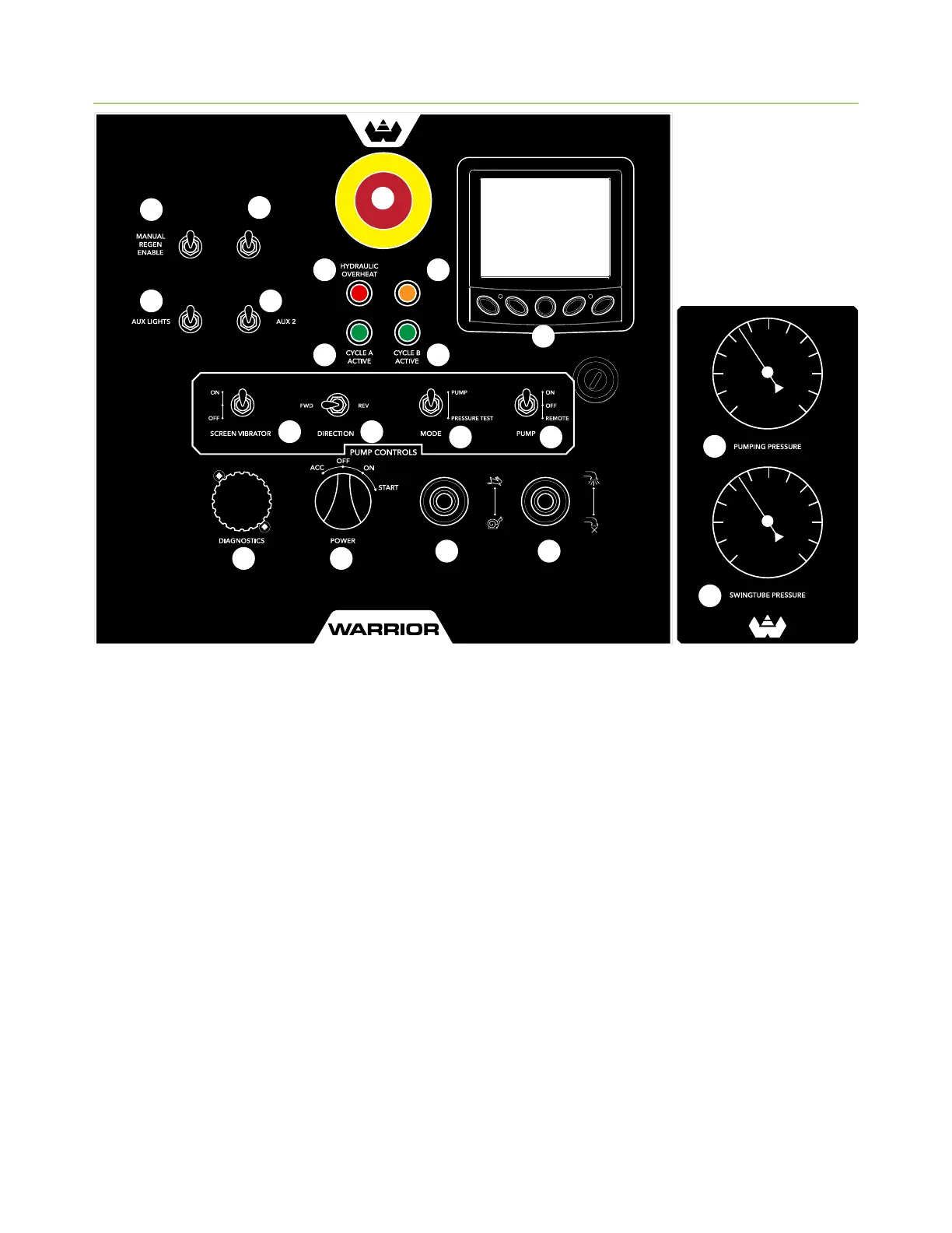
Control Panel
Emergency Stop Button (1)
Push this button in case of emergency. It will cause the
machine to terminate all functions.
Manual Regen Switch (2)
Switch enables operator to perform a manual regen
via Powerview monitor. Not required for normal
machine operation.
Safety Switch Override (3)
Switch bypasses hopper safety switch in case of
emergency or switch failure. Switch must never be
used for operating purposes.
Aux Lights (4)
Switch used for optional hopper lighting package.
Aux 2 (5)
Switch used for optional functions.
Hydraulic Fluid Overheat Alert (6)
Light illuminates when the hydraulic fluid temperature
exceeds the normal operating range (>180°).
FLOW CONTROLENGINE SPEED
CIRCUIT
ACTIVE
FAST
SLOW
SAFETY
SWITCH
OVERRIDE
E
M
E
R
G
E
N
C
Y
0 6000
0 6000
3
6 7
8 8
9
10 11
12
14 15
16 17
18
19
13
1
2
4 5
Circuit Active Light (7)
Light illuminates when hopper safety sensor is
engaged when grate is closed and hydraulic circuit is
powered.
Cycle A/B Light (8)
Light illuminates to show which drive cylinder is active.
PowerView Display (9)
Multifunction display provides information such
as engine speed, active regeneration, exhaust
temperature, diesel exhaust fluid level, error codes,
and service reminders.
Hopper Screen Vibrator Switch (10)
Activates the optional hopper screen vibrator if
equipped.
Pump Forward/Reverse Switch (11)
Switch is used for forward or reverse pumping.
Forward is normal pumping operation.