LEONARDO DATALOGGER
User manual
12
Turn off the inverter by performing the shutdown procedure as per manual.
1. The first step consists on removing the front plastic cover of the Leonardo System inverter. This cover is
fixed by 4 rivets on the sides of the metal casing. The rivets can be removed with a drill and 4mm drill bit.
After removing the rivets, the cover is easily removed, pulling it upwards and then pulling it forward.
2. The second step consists on conncecting the update calbe (Pic. 15).
3. The energy manager is fixed on the side of the Leonardo inverter. Connect the pair
of white / blue wires to the terminal block next to the network cable, according to
the following sequence:
- Pin.1 – void
- Pin.2 – white/blue wire → B in plug
- Pin.3 – blue wire → A in plug
- Pin.4 – void
Pic.16 Energy Manager Connection
4. The internal controllers are located at the top of the inverter.
5. Connect the pair of white / brown wires to the RS485 regulator terminal in this way:
- Pin.1 - void
- Pin.2 – brown wire → A in plug
- Pin.3 – white/brown wire → B in plug
The operation must be repeated for both controllers.
6. Set the ID addresses, keeping pressed for 1 sec. the two black keys and accessing
the SETUP pages. Set the address no.2 and no.3;
Remove the rectangular dowel at the base of the inverter housing and insert the
RJ45 socket.
Attention: the RJ45 socket must be fixed as shown in the picture;
Pic.17 RJ45 Plug on the Panel
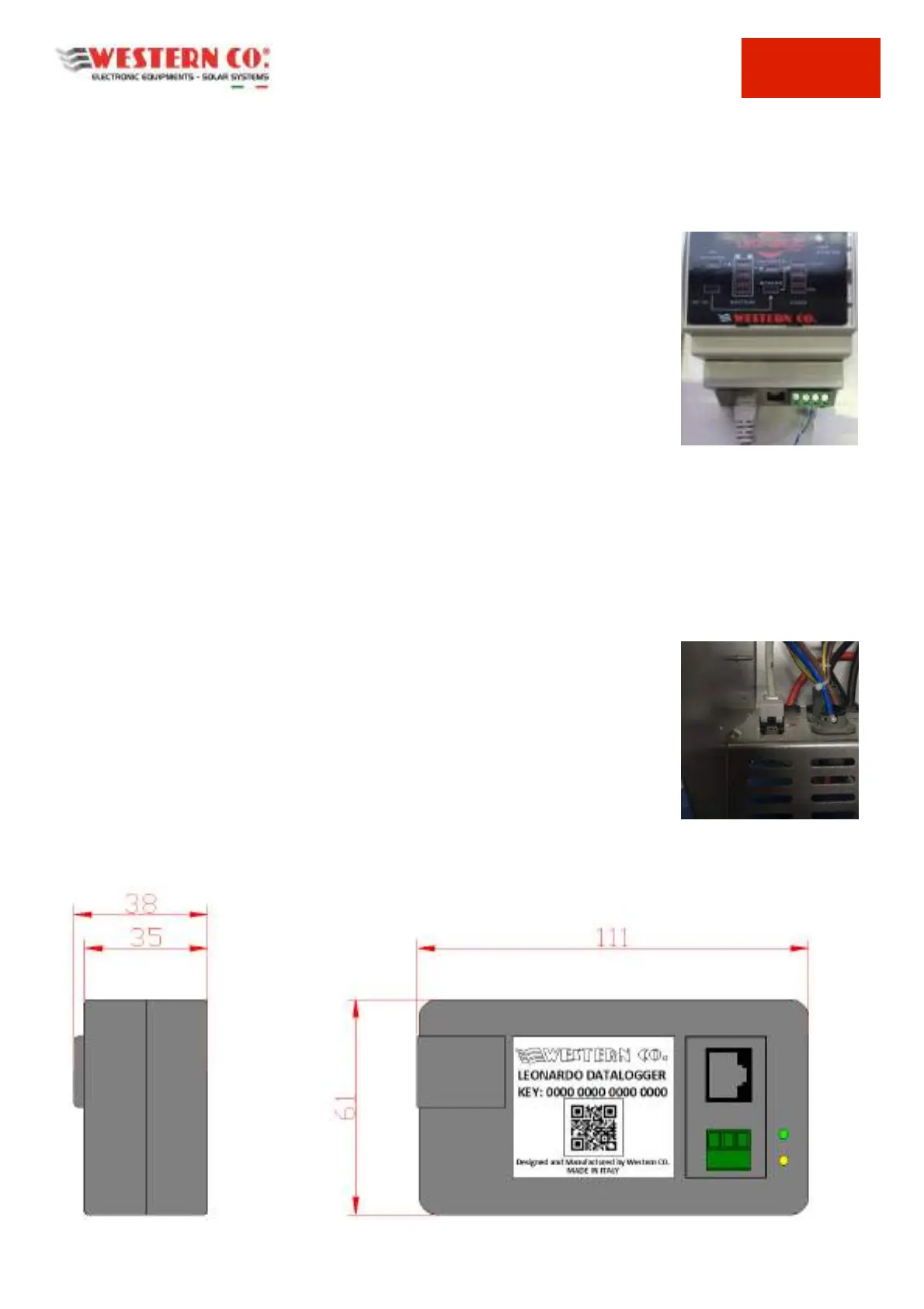
Mechanical Characteristics
Pic. 18 Mechanical Characteristics