1-2
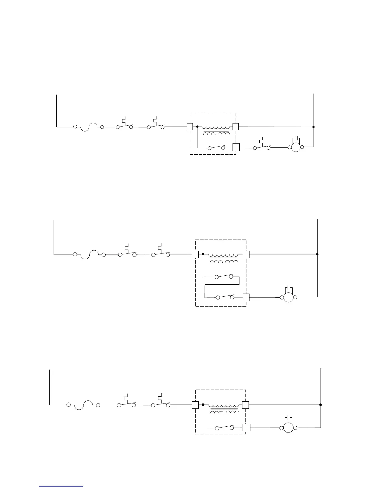
The normally-closed (N.C.) contacts of relay 4 provide a potential circuit for the Base Thermal
Fuse. If the base of the oven exceeds 133˚F, the thermal fuse contacts close, and a circuit for
the low-speed side of the blower motor is completed, which turns the motor on. The low-speed
blower will operate until the base temperature drops below 104˚F and opens the thermal fuse
contacts, and turns off.
N
L1
20A LINE
FUSE
CAVITY
THERMAL
FUSE
MAGNETRON
THERMAL
FUSE
BK
BK
BK
RELAY 4
BASE
THERMAL
FUSE
W
BL
YL
LOW-VOLTAGE
TRANSFORMER
W
BLOWER
MOTOR
RD
MICROCOMPUTER
BOARD
3 1
11
CAPACITOR
RD RD
(C)(HIGH)
When the low-speed fan is selected by the user at the control panel, relay 3 and the normally-
closed (N.C.) contacts of relay 4, complete the circuit to the low-speed windings of the blower
motor and turn it on.
N
L1
20A LINE
FUSE
CAVITY
THERMAL
USE
MAGNETRON
THERMAL
FUSE
BK
RDBK
RELAY 4
W
BL
PK/W
LOW-VOLTAGE
TRANSFORMER
BLOWER MOTOR
RD
RELAY 3
MICROCOMPUTER
BOARD
3 1
9
CAPACITOR
RDRD
(LOW)
(C)
When the high-speed fan is selected by the user at the control panel, the normally-open (N.O.)
contacts of relay 4 complete the circuit to the high-speed windings of the blower motor and turn
it on.
N
L1
20A LINE
FUSE
CAVITY
THERMAL
FUSE
MAGNETRON
THERMAL
FUSE
BK
RD
BK
RELAY 4
W
BL
BK
LOW-VOLTAGE
TRANSFORMER
BLOWER MOTOR
RD
MICROCOMPUTER
BOARD
3 1
13
CAPACITOR
RDRD
(HI) (C)