3-19
© 1997 Whirlpool Corporation
Cooking Products Service Manual
Original March, 1997 4322167
Page 3-19
TEST PROCEDURE RESULTCOMPONENT
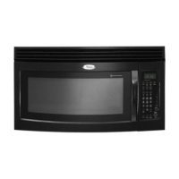
Terminal-To-Terminal
Set the ohmmeter to the
R x 10 k
scale, and measure the resistance
across the capacitor terminals.
High-Voltage Capacitor a) Normal - The meter indi-
cates several ohms, then
gradually returns to in-
finity.
b) Abnormal - The meter
indicates infinity, or zero
ohms (a short) immedi-
ately.
Terminal-To-Case
Set the ohmmeter to the
R x 1
scale, and measure the resistance
between each terminal and the
case.
a) Normal - The meter indi-
cates infinity.
b) Abnormal - The meter
indicates zero ohms, or
a short.
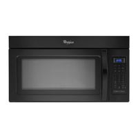
Blower Motor Capacitor
Terminal-To-Terminal
Set the ohmmeter to the
R x 10 k
scale, and measure the resistance
across the capacitor terminals.
a) Normal - The meter indi-
cates several ohms, then
gradually returns to in-
finity.
b) Abnormal - The meter
indicates infinity, or zero
ohms (a short) immedi-
ately.
a) Normal - The meter indi-
cates several ohms.
b) Abnormal - The meter
indicates infinity, or zero
ohms (a short).
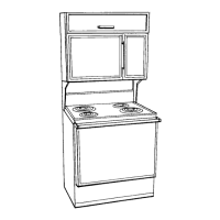
Forward Continuity
Set the ohmmeter to the
R x 1
scale, and measure the forward
resistance across the rectifier ter-
minals with the (+) lead touching
the anode and the (–) lead touch-
ing the cathode.
High-Voltage Rectifier
a) Normal - The meter indi-
cates infinity.
b) Abnormal - The meter
indicates infinity, or zero
ohms (a short).
Reverse Continuity
Set the ohmmeter to its highest
scale, and measure the reverse
resistance across the rectifier ter-
minals with the (+) lead touching
the cathode and the (–) lead touch-
ing the anode.
CAPACITOR
CATHODE
ANODE
RECTIFIER
DIODE