Do you have a question about the Whirlpool ADG 751 and is the answer not in the manual?
| Brand | Whirlpool |
|---|---|
| Model | ADG 751 |
| Category | Dishwasher |
| Language | English |
Details dimensions for built-in appliances and specifications for wooden doors.
Specifications for water softener, inlet pressure, and flow rates.
Provides voltage, frequency, power, fuse, and spray pump motor details.
Information on timer functions, wash programs, and energy efficiency ratings.
Details for the drain pump motor and heating element.
Information on temperature sensors, water inlet valve, and regenerating valve.
Details on reed contacts for salt/rinse aid and the water leakage floater switch.
Details on actuator functionality and water quantity settings for regeneration.
Table outlining salt consumption and regeneration cycles based on water hardness.
Lists structural elements, door fittings, and fixing components with their 12NC codes.
Details for upper, lower, and cutlery baskets, including rollers and holders.
Lists electrical components, control boards, switches, and motors with their 12NC codes.
Components related to water inlet, drain, and sealing, such as valves, hoses, and gaskets.
Lists spare parts including microfilters, hoses, drain connectors, and various gaskets.
Details screws, covers, plates, strips, and accessory items like jugs.
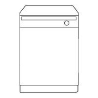
Diagram showing the main external and internal structural components of the dishwasher.
Illustration of basket assemblies and various smaller components.
Diagram illustrating spray arms, baskets, and water-related system parts.
Illustration of the control panel, motor housing, and related sub-assemblies.
Illustrates connections for the main switch, user control board, and associated wiring.
Diagrams for door switch, thermostat, magnet valve, pumps, and heating element wiring.
Shows terminal block connections and provides wire color codes for identification.
Circuit diagram for control module K1+K2, power supply, and main components.
Illustrates circuits for door lock, float switch, water level regulator, and spray pump.
Provides a key for various electrical components and their functions within the circuit.
Details on timer functions, temperature, fill quantity, and time for test programs.
Explanation of LED behavior for heating, filling, NTC errors, and passive/active test modes.
Instructions for initiating and executing active test mode, including error indication.