6-3
CONTROL PANEL TEST LOCATIONS
COMPONENT
FRONT/REAR
SERVICEABLE
CHECK POINTS RESULTS
Door Switch
Front
Front
Front
Front
Front
Front
Front
Front
P7-2 (BR) to P7-1 (TAN)
Door Open = Closed Circuit
Door Closed = Open Circuit
Door Lock Solenoid
(with Door Closed)
P6-1 (Y) to P6-2 (W)
50 Ω
Oven Temperature Sensor
P7-4 (V) to P7-6 (GN)
1080 Ω @ 21°C (70°F)
Blower
Rear
P1-5 (GY) to Neutral (W)
14 Ω to 18 Ω
Oven Light Transformer
Primary Winding
Secondary Winding
40 Ω to 45 Ω
Less than1 Ω
Oven Shutdown
Thermal Fuse
Rear
P5-2 (OR) or P5-3 (R)
to Red Wire at Terminal Block
Closed Circuit
Bake Element
Rear
P5-3 (R) to Red Wire at Terminal Block
P5-2 (OR) to Red Wire at Terminal Block
P5-1 (BU) to Red Wire at Terminal Block
P5-4 (Y) to Red Wire at Terminal Block
25 Ω to 30 Ω
Inner Broil Element
45 Ω to 55 Ω
Outer Broil Element
45 Ω to 55 Ω
Convection Ring Element
28 Ω to 35 Ω
Convection Fan Motor
Rear P1-6 (OR) to Neutral (W) 8 Ω to 12 Ω
Meat Probe Jack
Rear
P7-7 (GN) to P7-8 (Y)
Probe into Jack - Check for
78k Ω @ Room Temperature
Latch Switch
P7-3 (BU) to P7-1 (TAN)
Door Unlocked = Open Circuit
Door Locked = Closed Circuit
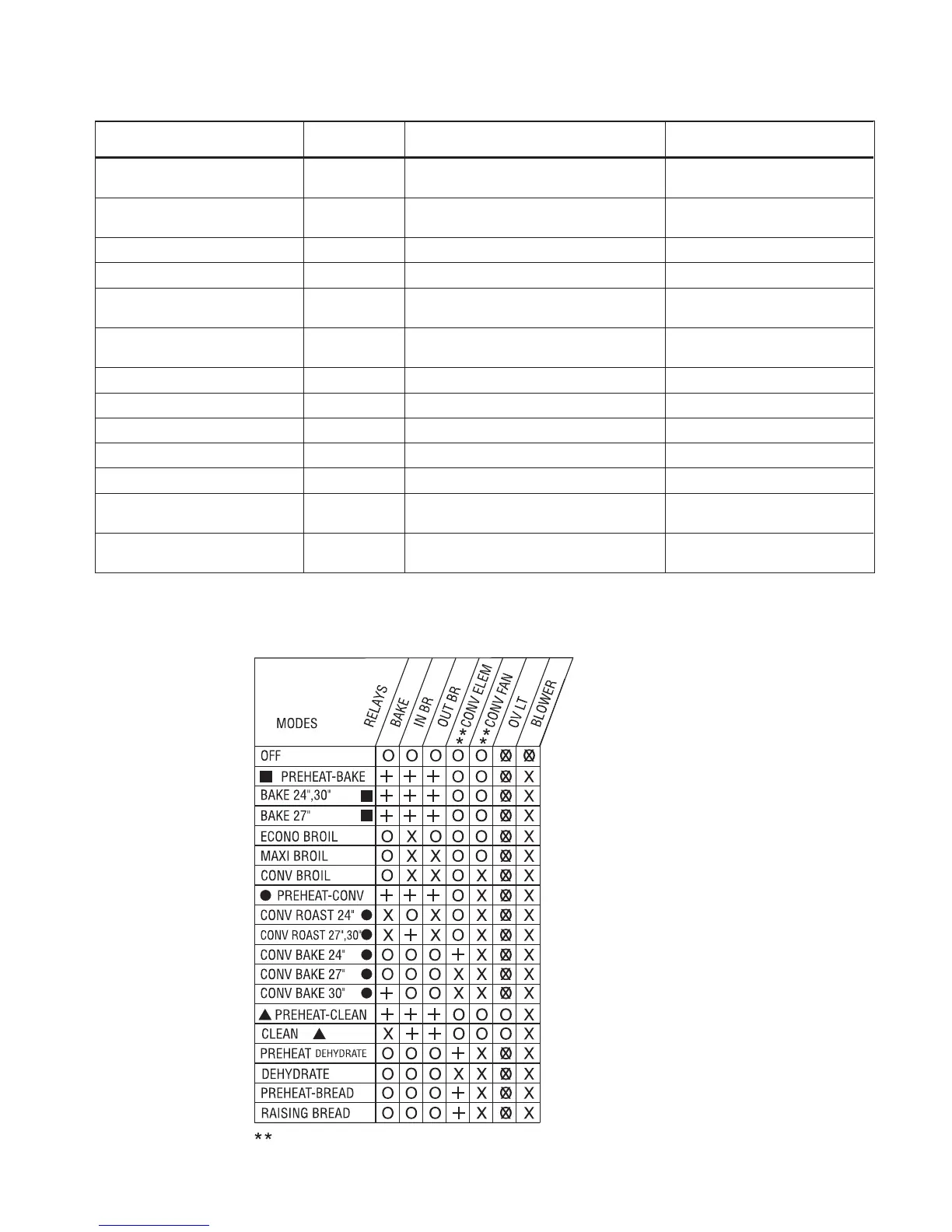
RELAY LOGIC CHART
RELAY LOGIC KEY
- ON
- OFF
- CYCLING (MAX PERIOD = 60SEC)
- ON OR OFF
O
X
OX
+
Thermal Convection Models Only



 To Next Page