For Service Technician Use Only
DIAGNOSTICS
2-4
n
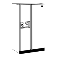
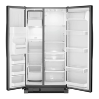
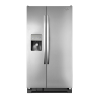
Multi-Door Freestanding Refrigerator
Press SW1 and SW2 simultaneously for 3 seconds. Release both buons when you hear the CHIME indicator.
Unit must not be in Lockout prior to entering SERVICE DIAGNOSTIC MODE. The display will show 01 to indicate the control is in step 1
of the diagnoscs roune.
■ Press SW1 and SW2 simultaneously for 3 seconds.
■ Disconnect the product from power.
■ Allow 20 minutes to pass.
■ Following the exit of the diagnosc mode, the controls will
then resume normal operaon.
NOTES:
■ Cooling diagnoscs are steps 1 through 6 and 32 through 41.
■ Dispensing diagnoscs are steps 8 through 31.
■ Each step must be manually advanced.
■ Press SW5 to move to the next step in the sequence.
■ Press SW4 to back up in the sequence to the previous step.
■ Diagnoscs will begin at Step 1.
■ Each step is displayed in the two digits of the dispenser user
interface display.
■ The step results are displayed in the two digits on dispenser
user interface display 2 seconds aer the step number
is displayed. An amber order lter light will be shown to
designate that the step number is being displayed and a red
replace lter light will be shown to designate that the status
of the step is being displayed.
■ All buon and pad inputs shall be ignored and all inputs shall
be o except as described in the acons for each step.
No-Load Performance, Controls in Normal Posion
kW/24 hr/±0.4
Percent Run
Time/±10%
Cycles/24 hr
/±10
Refrigerator
Compartment
Average Food
Temperature
±4°F/2°C
Freezer
Compartment
Average Food
Temperature
±5°F/3°C
Ice Maker
Compartment
Average Food
Temperature
±5°F/3°C
Ambient
°F/°C
70°F 90°F 110°F 70°F 90°F 110°F 70°F 90°F 110°F 70°F 90°F 110°F 70°F 90°F 110°F 70°F 90°F 110°F
21°C 32°C 43°C 21°C 32°C 43°C 21°C 32°C 43°C 21°C 32°C 43°C 21°C 32°C
43°C 21°C 32°C 43°C
29 Cu. Ft.
1.3 1.9 3.6 49.4% 85.3% 89.2% 28.6 18.8 8.6
36.8°F 36.4°F 36.8°F -2.1°F 1.6°F 7.3°F 24.5°F 22.2°F 21.6°F
2.7°C 2.4°C 2.6°C -18.9°C -18.7°C -13.7°C -4.2°C -5.5°C -5.8°C
Temperature Relaonship Test Chart
Refrigerator
Evaporator Inlet/
Outlet ±5°F/3°C
Freezer Evaporator
Inlet/Outlet
±5°F/3°C
Sucon Line
/±7°F/4°C
Average Total
Waage ±10%
Sucon Pressure
±2 PSIG *
Head Pressure
±5 PSIG *
Ambient
°F/°C
70°F 90°F 70°F 90°F 70°F 90°F 70°F 90°F 70°F 90°F 70°F 90°F
21°C 32°C 21°C 32°C 21°C 32°C 21°C 32°C 21°C 32°C 21°C 32°C
29 Cu. Ft.
22.2°F 23.2°F -5.7°F -6°F 86.5°F 104°F
38 67.1 31.1 31.3 121 161.3
-5.4°C -4.9
°C -20.9°C -21.1°C 30.3°C 40°C
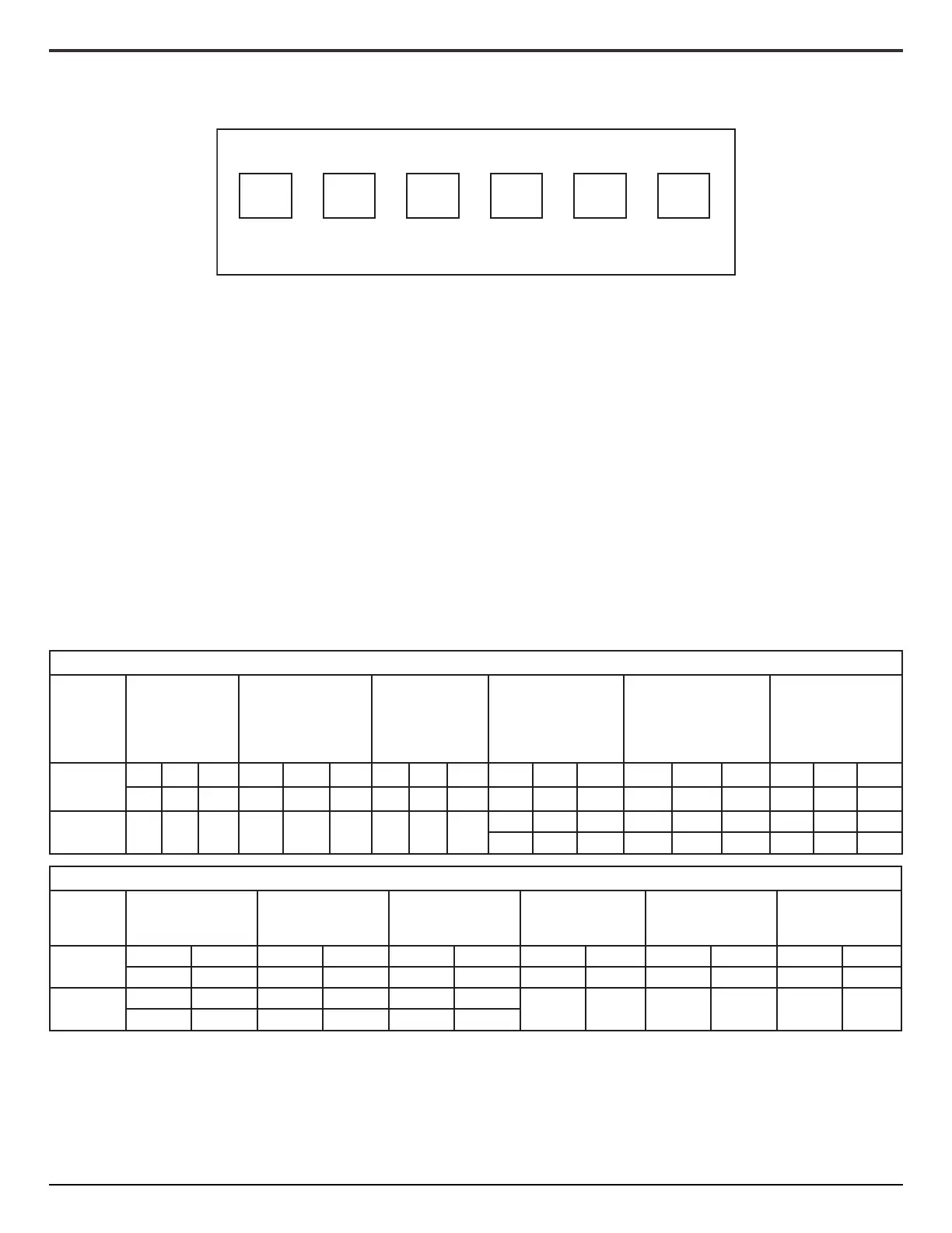
SWITCH DIAGRAM
SW1 SW2 SW3 SW4 SW5 SW6