For Service Technician Use Only
DIAGNOSTICS
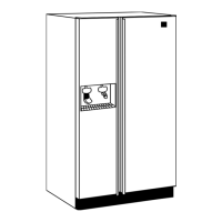
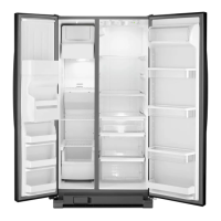
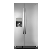
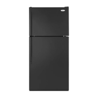
Multi-Door Freestanding Refrigerator
n
2-5
Diagnostic Load (Service) Test
■ The board will check the resistance value of the thermistor
and display ashes results on the Temp Display.
(01 = Pass, 02 = Open, 03 = Short).
■ The board will check the resistance value of the thermistor
and display the results on the Temp Display.
(01 = Pass, 02 = Open, 03 = Short).
■ Control the RC & FC Evaporator Fan Motors by depressing
SW3. (01 = Both Fan Mtr. o, 02 = FC Fan on).
■ Depress SW3 once to advance. Step 3 will ash quickly and
advances to steps 13/23 very quickly. The result is RC Fan on,
Pantry Air Damper on. Pantry Air Damper will open and close
automacally. (13 = Damper Open, 23 = Damper Closed.
Verify air ow inside pantry on le hand side when damper is
open, 912 displayed). Air ow in pantry will cease when 23 is
displayed.
■ Depress SW3 to advance to last step.
(04 = Both RC & FC fans on).
■ There will be a delay of 3 seconds before start of sub step
01. Each step is med and will be automacally proceed to
the next step. User will not be allowed to exit step. If exit is
aempted, an invalid chime will be produced.
■ Control the Sealed System loads selecng SW3.
01 = Inialize Dual Evap Valve in home posion (4 min)
02 = Close both RC & FC Evap Valve (1 min)
03 = Turn compressor ON (1 min)
04 = Keep compressor ON, drive the valve to RC posion &
turn RC fan ON
05 = Keep compressor ON, drive the valve to FC posion &
turn FC fan ON. Verify air ow from the evaporator fan.
NOTE: Advance quickly through step 4 keep from locking
in. Once locked in you can’t exit, must wait ten minutes
approximately.
■ Inial Display, 02 = Minimum speed
■ Depress SW3, Display = 03, Compressor ramps up to Max
speed. When Max speed reached, 01 displayed.
■ Depress SW3, Display = 04 Speed ramps down from Max to
minimum speed. When Min speed reached, 02 displayed.
■ Switch on the defrost heater, wait 0.5 seconds and read the
status of bimetal/sensor. Display will be blank unl a valid
reading is displayed.
01 = Bimetal Closed/Sensor Short
02 = Bimetal Open/Sensor Open
03 = Pass (only in case a defrost sensor is present).
■ Set the Defrost Mode using CHANGE SETTING KEYs. This
value shall be stored on EEPROM (in the next Power-up the
Defrost Mode shall be inialized according to this seng.)
Inial display 01 = ADC ON
02 = Basic Mode ON (8 hour mer).
■ Verify that all LED indicators and UI display digits turn on
automacally. All indicators ON for 30 second meout.
■ Displays the user Interface Buons and Ice and Water Pads
status as described in the Component Status Indicator
column below.
NOTE: Do not use SW4 and SW5 as these are used only to
navigate through the Service Diagnoscs.
NOTE: SW4 and SW5 are used for navigaon and are not
displayed.
■ Pressing SW3 will change the dispenser lighng seng from
OFF (0%) to ON (100%) to DIM (50%) Status indicator is Blank.
■ Displays the Ice Bin Status in real me on the UI display.
Verify that the full and not full levels display correctly.
(01 = Bin Full or not present, 02 = Bin Not Full).
■ Displays the RC Door status in real me on the UI display.
Verify that the open and close status display correctly.
(01 = FC Door Open, 02 = FC Door Closed).
■ Displays the FC Door status in real me on the UI display.
Verify that the open and close status display correctly.
(01 = FC Door Open, 02 = FC Door Closed).
■ Displays the Ice Door stepper motor state on the UI display.
Press ice paddle and verify that the mechanical operaon of
the ice door corresponds to the component status indicator.
NOTE: Ice door will have a delay in closing aer an ice paddle
is released.
(01 = Closed, 02 = Opening, 03 = Open, 04 = Closing).
■ Control the Ice Maker Fill Tube Heater selecng SW3 (toggle
between On and O) (01 = ON, 02 = O).
■ Displays in two sequenal ashes the total water usage rang
in gallons for the water lter on the UI display. Wait unl
dash is displayed which means end of the number.
(00/0- to 99/9-) Example: 123 will be displayed as .
Press
SW1
SW2
SW3
SW6
Dispenser Pad
Digit 1
1
2
3
6
Digit 2
1