For Service Technician Use Only
DIAGNOSTICS
2-6
n
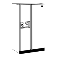
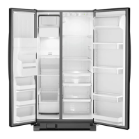
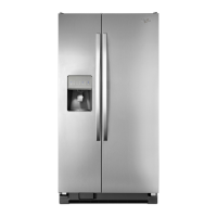
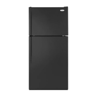
Multi-Door Freestanding Refrigerator
■ Displays in two sequenal ashes the total me rang in
days for the water lter on the UI display. Wait unl dash is
displayed which means end of the number. (00/0- to 99/9)
Example: 123 will be displayed as .
■ Displays in two sequenal ashes the current water lter
status in gallons used since last rest on the UI display. Wait
unl dash is displayed which means end of the number.
(00/0- to 99/9-) Example: 123 will be displayed as .
■ Displays in two sequenal ashes the current water lter
status in days since last reset on the UI display. Wait unl
dash is displayed which means end of the number. (00/0- to
99/9) Example: 123 will be displayed as .
■ Display in two sequenal ashes the current mes the water
lter was rest on the UI display. Wait unl dash is displayed
which means the end of the number. (00/00/00 to 99/99/99)
Example: 123 will be displayed as .
NOTE: Not normally used.
■ Displays in three sequenal ashes the Main Control
soware version on the UI display.
NOTE: This is repeatedly displayed during all me in this step.
00/00/00 to 99/99/99.
NOTE: Not normally used.
■ Displays in three sequenal ashes the Main Control
soware version on the UI display. NOTE: This is repeatedly
displayed during all me in this step. 00/00/00 to 99/99/99.
NOTE: Not normally used.
■ Displays in three sequenal ashes the low voltage soware
version on the UI display. NOTE: This is repeatedly displayed
during all me in this step. 00/00/00 to 99/99/99.
NOTE: Not normally used.
■ Displays in three sequenal ashes the Dispenser UI Control
soware version on the UI display. NOTE: This is repeatedly
displayed during all me in this step. 00/00/00 to 99/99/99.
■ This is an internal board test, The board will check the
resistance value of the thermistor and display the results.
(01 = Pass, 02 = Open, 03 = Short).
■ Relave Humidity Test
(Humidity % Value 0-99 = pass or Er = Fail).
■ Set the Vercal Mullion Heater Sensor Mode by selecng
SW3. (01 = Sensor Operaon On, 02 = Sensor Operaon O
(Heater on 100%)).
■ Control the Vercal Million Heater selecng SW3.
(Toggle between On and O) (01 = ON, 02 = OFF).
■ Check for fan operaon. Control Ice Box Fan using SW3.
Display the status on Temp Display.
(01 = ON, 02 = OFF). Verify air ow from the IB fan.
■ The board will check the resistance value of the thermistor
and display the results on the Temp Display.
(01 = Pass, 02 = Open, 03 = Short).
■ Set the Forced Defrost Mode by selecng SW3, OF = No
forced Defrost, Sh = Short Defrost, Lo = Long defrost.
■ The board will check the resistance value of the thermistor
and display the results on the Temp Display.
(01 = Pass, 02 - Open, 03 = Short.)
■ Set the Horizontal Mullion Heater Sensor Mode by selecng
SW3. (01 = Sensor Operaon On, 02 = Sensor Operaon O
(Heater on 100%).
■ Control the Horizontal Mullion Heater selecng SW3.
(Toggle between On and O) (01 = ON, 02= OFF).
NOTE: Not normally used.
■ Displays in three sequenal ashed the Dispenser UI Control
soware version on the UI display.
NOTE: This is repeatedly displayed during all me in this step.
00/00/00 to 99/99/99.
■ Aer an inial 3 second delay, displays the Ice Maker water
ll stat on the UI display. Press SW3 to start a water ll.
Pressing SW3 will toggle between ON and PAUSE.
(02 = O, 03 = On, 04 + Paused).
■ Displays the status of the water dispense valve. Press the
water pad to iniate a water dispense. (00 = Water Dispense
Valve O, 01 = Water Dispense Valve On).
■ Displays acve Ice Maker Error Codes on the UI display.
(E0 = No Errors, E1 = No Cooling, E2 = Motor Lost Posion,
E3 = Heater Timeout, E4 = Dry Cycle, E5 = Timed Ice Making).
■ Press SW3 to acvate a Harvest sequence. Digit 1 displays
the state of the sequence. Digit 2 displays the outcome of the
sequence. Once iniated, the sequence cannot be exited.
Digit 1
0 = Heater and Motor OFF,
1 = IM Heater ON,
2 = Motor Rotang CW unl it nds home posion.
Digit 2
0 = In Progress,
1 = Harvesng Completed,
2 = Harvesng not completed, Doors must be closed.
NOTE: Harvesng Not Completed does not exit the step, but
indicates the meout of 70 seconds has passed.