Page 14 | 1-800-343-9463
WCM 021219
Accessing Service Menu
Hold SERVICE for 3 seconds
Cycle through menu options – UP/DOWN
Press SET to see number of alarms
Press SET again to return to menu options
Exit menu - UP and SET
+
Accessing Alarm Code Information
Press and release ALARM
Cycle through menu options – UP/DOWN
Press SET to see number of alarms
Press SET again to return to menu options
Exit menu - UP and SET
+
Emerson
™
Electronic Unit Controller
Quick setup and troubleshooting guide
Low Pressure Cut-In Low Pressure Cut-Out
Alarm Description
PoF Keypad locked
Pon Keypad unlocked
P1 Suction probe failure
P2 Condenser probe failure
P3 DLT probe failure
HA High condenser temperature alarm
dLt DLT temperature alarm
dLL DLT lock alarm
HP High pressure trip alarm
HPL High pressure trip lock-out alarm
EE Module Failure
LOC Number of lock-outs
Code Description
StH CompressorStarts –1000 -999999
StL Compressor Starts –0 -999
CHH CompressorHours -1000 -999999
CHL Compressor Hours -0 -999
F1H Fan 1 Hours -1000 -999999
F1L Fan 1 Hours-0 -999
F2H Fan 2 Hours -1000 -999999
F2L Fand 2 Hours -0 -999
Example: If StH=12 and StL=500, the total num-
ber of compressor starts=12,500
Adjusting Low Pressure Settings
Hold DOWN and SET simultaneously for 3 seconds
to enter menu (PSI light will ash)
Cycle through menu options – UP/DOWN
Select function – SET
Adjust value – UP/DOWN
Store function - SET
Exit menu - UP and SET
+
+
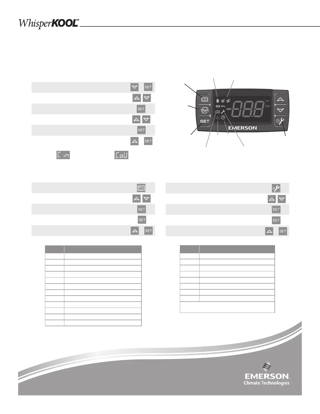
Book of Alarms –
to enter alarm menu
Fan light 1 & 2
(Fan cycle units only)
Service – to enter
service menu
Service
menu
Run
time
Active
alarm
Alarm
history
Set – Displays
set point. In
programming
mode, it con rms
an operation
Compressor
Module Restart –
push to reset
the HPL, DLL
lock out faults
(cycle power)
When light is on, feature or component is on or active
For more information visit
EmersonClimate.com/ElectronicUnitController
or call 1-888-367-9950
Note: After 15 seconds of inactivity the controller will revert
to the default display.