2
INSTALLATION
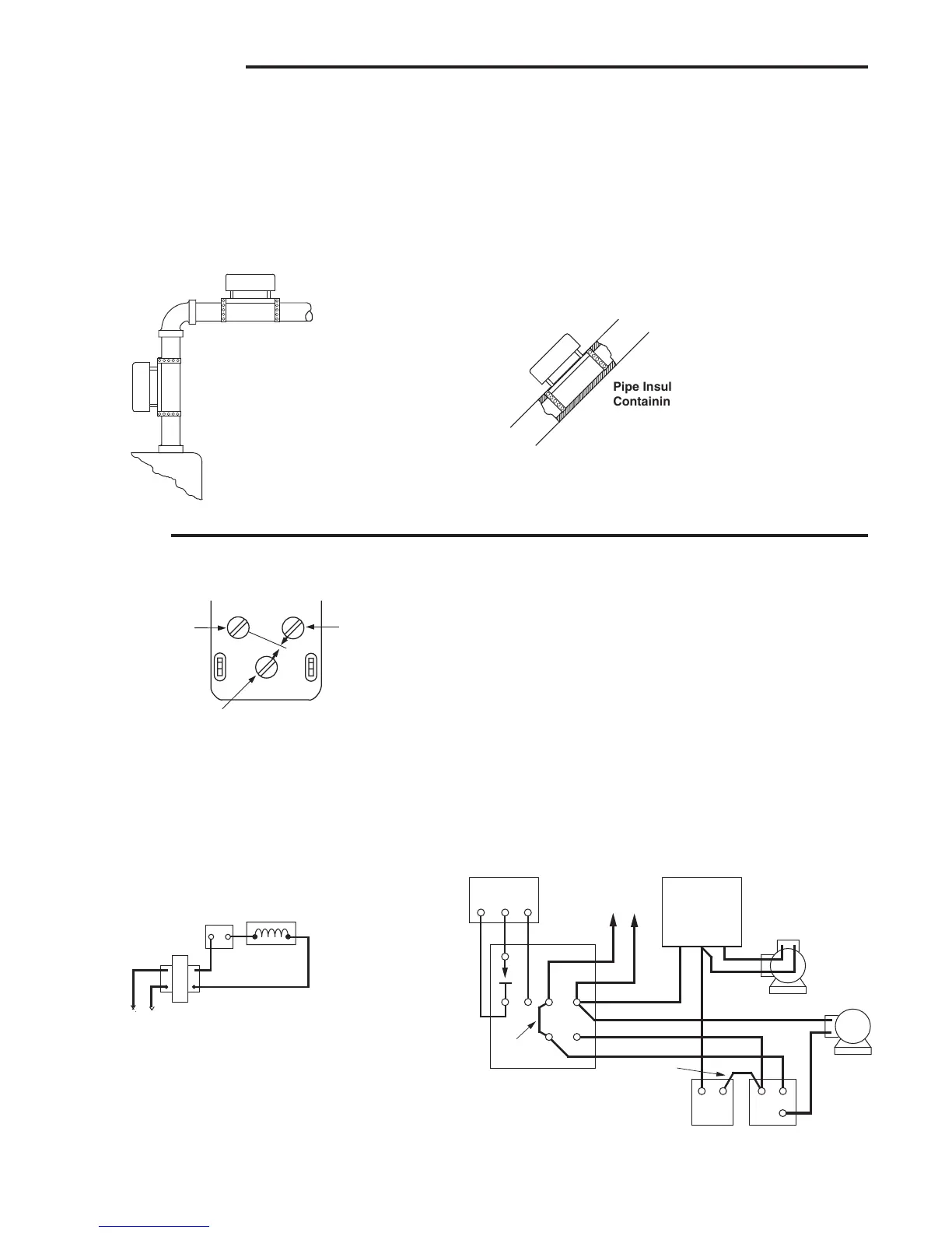
Pipe Insulation Should Cover Shield
Containing Element.
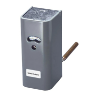
Convenient Installation – May be mounted
vertically, horizontally, or on an angle. Will
not affect operation of control.
WIRING
All wiring should be done according to local and national electrical codes.
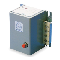
This control has a single-pole, double-throw snap action switch.
The top left-hand terminal (red) is the common terminal. The top
right-hand terminal (blue) has open-on-rise switch action. The
bottom centre terminal (white) has close-on-rise switch action.
Refer to the wiring diagram supplied by the boiler or burner
manufacturer, or to the suggested circuits included with the
primary control. The information below shows the terminals to
use for the various applications.
Limit Control: When used as either a high limit control or as a
low limit control, use the open-on-rise terminals (red and blue).
Circulator Control: When used as a circulator control, use the
close-on-rise terminals (red and white).
Combination Low Limit and Circulator Control: For this
application, all 3 terminals are used. The wiring diagram below
shows a typical circuit for a hot water system having a boiler
with tankless domestic coil.
Diagram for Boiler with Tankless Domestic Coil
R
B
W
W
1
4
2
3
B
R
X X
3-WIRE THERMOSTAT
(USE W-B FOR
2-WIRE THERMOSTAT)
TYPE 668 OIL
BURNER CONTROL
(LINE VOLTAGE)
IGNITION
TRANS.
BURNER
MOTOR
CIRCULATOR
MOTOR
HIGH
LIMIT
JUMPER
JUMPER
TYPE 1127
LOW-LIMIT
CIRCULATOR
CONTROL
N
LINE
HOT
X
X
Diagram for
Gas-Fired System
24 VAC
GAS VALVE
HIGH
LIMIT
TRANS.
X
X
RED
WHITE
BLUE
COMMON
CLOSE ON RISE
OF TEMPERATURE
OPEN ON RISE
OF TEMPERATURE
If the boiler manufacturer recommends a control location, follow
such recommendations. If none is offered, the following informa-
tion gives suggested locations.
On a domestic heating system, surface mounted controls may
be attached to either a horizontal or a vertical riser approximately
18 inches above the boiler.
On a unit heater application, they may be attached to the base
of the coil directly in the air path or on the return line.
Installation Rules:
1. Remove the insulation on the pipe or tank where the control
is to be mounted.
2. All rough spots, scale, rust, or paint should be removed with
a file or similar tool.
3. Mount the control to the pipe by means of the two clamps
provided. They should be pulled up snugly.
4. Replace the insulation, entirely embedding the shield which
is around the sensitive element of the control.
 Loading...