Do you have a question about the White Rodgers 1F58-72 and is the answer not in the manual?
| Brand | White Rodgers |
|---|---|
| Model | 1F58-72 |
| Stages | 1 Heat / 1 Cool |
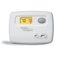
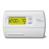
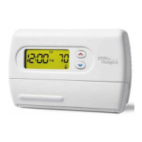
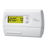
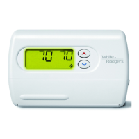
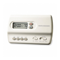
| Display Type | Digital |
| Voltage | 24 VAC |
| Backlight | Yes |
| Power Source | Battery |
| Terminal Designations | W, Y, G |
| Temperature Range | 40°F to 90°F |
Details the thermostat's purpose and basic operation for heat pump systems without automatic changeover.
Important safety warnings and cautions regarding electrical shock, voltage limits, and handling.
Specifies switch ratings, switch actions, and anticipator ratings for thermostat operation.
Provides technical details on circuit type, temperature range, and rated differential.
Guidelines for choosing an optimal location for accurate temperature sensing and thermostat performance.
Instructions for properly running thermostat wires to the selected installation site, avoiding obstructions.
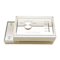
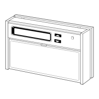
Steps for mounting the subbase securely and correctly, ensuring it is level.
How to connect the thermostat unit to the mounted subbase, ensuring all connections are snug.
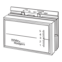
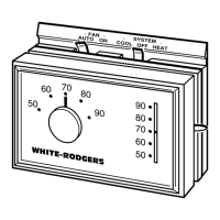
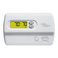
Details system functions based on fan/system switch positions and component operations.
Guide to measuring current draw and setting the adjustable anticipator for optimal heating cycles.
Procedures for recalibrating the thermostat if actual room temperature differs significantly from the setting.