EasyManua.ls Logo

White Rodgers 1F85-0477 User Manual

White Rodgers 1F85-0477
12 pages
To Next Page IconTo Next Page
Page #1 background imageLoading...
Page #1 background image
1
Blue 4” Universal Thermostat with
Automatic Heat/Cool Changeover Option
Single Stage, Multi-Stage or Heat Pump
Installation and Operating Instructions for Model:
FAILURE TO READ AND FOLLOW ALL INSTRUCTIONS
CAREFULLY BEFORE INSTALLING OR OPERATING
THIS CONTROL COULD CAUSE PERSONAL INJURY
AND/OR PROPERTY DAMAGE.
Save these instructions for future use!
APPLICATIONS
SPECIFICATIONS
Electrical Rating:
Battery Power .................................................... mV to 30 VAC, NEC Class II, 50/60 Hz or DC
Input-Hardwire ................................................... 20 to 30 VAC
Terminal Load ........................................................... 1.5 A per terminal, 2.5A maximum all terminals combined
Setpoint Range ......................................................... 45° to 90°F (7° to 32°C)
Differential (Single Stage) ......................................... Heat 0.6°F; Cool 1.2°F (adjustable)
Differential (Heat Pump) ........................................... Heat 1.2°F; Cool 1.2°F (adjustable)
Operating Ambient .................................................... 32° to +105°F (0° to +41°C)
Operating Humidity ................................................... 90% non-condensing max.
Shipping Temperature Range ................................... -40° to +150°F (-40° to +65°C)
Dimensions Thermostat ............................................ 3-7/8”H x 5-1/8”W x 1-1/4”D
www.white-rodgers.com
www.emersonclimate.com
1F85-0477 Thermostat
Model Programming Choices
1F85-0477
7 Day 5/1/1 Day
ATTENTION: MERCURY NOTICE
This product does not contain mercury. However, this product
may replace a product that contains mercury.
Mercury and products containing mercury must not be
discarded in household trash. Do not touch any spilled
mercury. Wearing non-absorbent gloves, clean up any spilled
mercury and place in a sealed container. For proper disposal
of a product containing mercury or a sealed container. Refer
to www.white-rodgers.com for location to send product
containing mercury.
To prevent electrical shock and/or equipment damage,
disconnect electric power to system at main fuse or
circuit breaker box until installation is complete.
CAUTION
!
THERMOSTAT APPLICATION GUIDE
Description
Heat Pump (No Aux. or Emergency Heat)
Yes
Heat Pump (with Aux. or Emergency Heat)
Yes
Systems with up to 2 Stages Heat, 2 Stages Cool
Yes
Heat Only Systems (with optional fan switch)
Yes
Millivolt Heat Only Systems – Floor or Wall Furnaces
Yes
Cool Only Systems
Yes
Gas or Oil Heat
Yes
Electric Furnace
Yes
Hydronic (Hot Water) Zone Heat – 2 Wires
Yes
Hydronic (Hot Water) Zone Heat – 3 Wires
Yes
Index Page
Installation 2
Wiring Connections 2
Wiring Diagrams 3
Thermostat Quick Reference 5
Installer Configuration Menu 6
Operating Your Thermostat 8
Programming 9
Troubleshooting 10
PART NO. 37-7050B
Replaces 37-7050A
1011
Question and Answer IconNeed help?

Do you have a question about the White Rodgers 1F85-0477 and is the answer not in the manual?

White Rodgers 1F85-0477 Specifications

General IconGeneral
TypeProgrammable Thermostat
DisplayLCD
Power SourceBattery or Hardwired
Voltage24 VAC
BacklightYes
Temperature Range45°F to 90°F (7°C to 32°C)
Weight0.5 lbs
Stages1 Heat, 1 Cool

Summary

APPLICATIONS

THERMOSTAT APPLICATION GUIDE

Guide to thermostat compatibility with various heating and cooling systems.

SPECIFICATIONS

INSTALLATION

Remove Old Thermostat

Instructions for safely removing the existing thermostat from the wall.

Installing New Thermostat

Step-by-step guide for mounting and connecting the new thermostat base.

Batteries

Guidance on installing and replacing the thermostat's AA alkaline batteries.

WIRING CONNECTIONS

TERMINAL DESIGNATION DESCRIPTIONS

Explanation of each terminal designation on the thermostat wiring base.

WIRING DIAGRAMS

Heat Pump Connections

Wiring diagrams for various heat pump system configurations.

Single Stage and Multi-Stage Connections

Wiring diagrams for single and multi-stage fossil fuel systems.

WIRING DIAGRAMS

Single Stage or Multi-Stage System (No Heat Pump) with Two Transformers

Wiring diagram for a two-transformer system without a heat pump.

3-Wire (SPDT) Heat Only Zone Valve Wiring

Wiring diagram for a 3-wire heat-only zone valve system.

THERMOSTAT QUICK REFERENCE

Home Screen Description

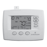
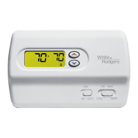
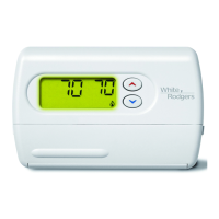
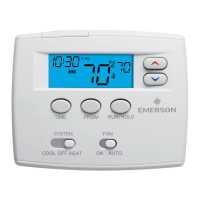
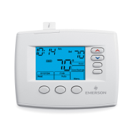
Explanation of the elements displayed on the thermostat's home screen.

Programming and Configuration Items

Overview of key indicators and functions within the thermostat interface.

INSTALLER/CONFIGURATION MENU

Keypad Lockout

Setting up keypad lockout to prevent unauthorized changes.

System Mode Configuration

Configuring the thermostat for different system types (Heat, Cool, Auto).

Filter Change-out Indicator

Enabling and setting the reminder for filter replacement.

INSTALLER/CONFIGURATION MENU

Cool Savings Feature

Adjusting the cooling savings feature for humidity control.

Energy Management Recovery

Enabling early start for heating or cooling to reach setpoint.

Temperature Limit Range

Setting maximum heat and minimum cool setpoint limits.

OPERATING YOUR THERMOSTAT

Choose the Fan Setting

Selecting between Auto and On fan modes for air circulation.

Choose the System Setting

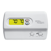
Selecting system modes: Heat, Off, Cool, Auto, or Emergency Heat.

Manual Operation (Bypassing the Program)

Overriding the programmed schedule with manual temperature settings.

PROGRAMMING

Set Current Time and Date

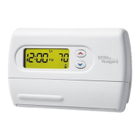
Procedure for setting the thermostat's internal clock and date.

Enter the Heating Program

Instructions for setting daily heating schedules and temperatures.

Enter the Cooling Program

Instructions for setting daily cooling schedules and temperatures.

PROGRAMMING

Worksheet for Re-Programming 7 Day and 5+1+1 Day Program

A template to plan custom heating and cooling schedules.

TROUBLESHOOTING

Reset Operation

How to reset the thermostat to factory settings after issues.

No Heat/No Cool/No Fan (common problems)

Common causes and corrections for system operation failures.

Thermostat Setting & Thermometer Disagree

Troubleshooting discrepancies between displayed and actual temperatures.

Related product manuals