Model Programming Choices
1F95-1291
7 Day 5/1/1 Day Non-Programmable
www.white-rodgers.com
Big Blue Humidity Universal Thermostat
with Humidity/Dehumidity Control and
Automatic Heat/Cool Changeover Option
PART NO. 37-6914D
Replaces 37-6914C
0905
Single Stage, Multi-Stage, Heat Pump
Installation and Operating Instructions
APPLICATIONS
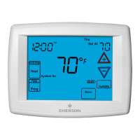
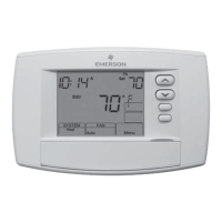
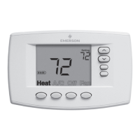
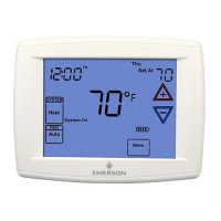
1F95-1291 Humidity Control Touchscreen Thermostat
SPECIFICATIONS
Save these instructions for future use!
FAILURE TO READ AND FOLLOW ALL INSTRUCTIONS
CAREFULLY BEFORE INSTALLING OR OPERATING THIS
CONTROL COULD CAUSE PERSONAL INJURY AND/OR
PROPERTY DAMAGE.
THERMOSTAT APPLICATION GUIDE
Thermostat
Confi guration Options
Thermostat
Applications
Maximum
Stages
Heat/Cool
Single Stage 1
No Heat Pump (SS1)
Gas, Oil, Electric, Heat Only,
Cool Only or Heat/Cool
Systems, 2 or 3 wire Hydronic
Zone (Hot Water or Steam)
Systems, 24 Volt or Millivolt
1/1
Multi Stage 2
No Heat Pump (MS2)
2/2
Heat Pump 1
Single Stage Compressor
Heat Pump (HP1)
Single Stage Compressor
Heat Pump Systems - up to 2
Stages Aux./Emergency Heat
3/1
Heat Pump 2
Two Stage or Two
Compressor Heat Pump
(HP2)
Two Stage or Two Compressor
Heat Pump systems - up to 2
Stages Aux./Emergency Heat
4/2
ATTENTION: MERCURY NOTICE
This product does not contain mercury. However, this prod-
uct may replace a product that contains mercury.
Mercury and products containing mercury must not be
discarded in household trash. Do not touch any spilled
mercury. Wearing non-absorbent gloves, clean up any
spilled mercury and place in a sealed container. For proper
disposal of a product containing mercury or a sealed
container of spilled mercury, place it in a suitable shipping
container. Refer to www.white-rodgers.com for location to
send the product containing mercury.
Index Page
Installation 2
Wiring Diagrams 3
Thermostat Quick Reference 5
Installer Confi guration Menu 6
Operating Your Thermostat 10
Programming 12
Troubleshooting 16
Electrical Rating:
Battery Power . . . . . . . . . . . . . . . . . . . . . . . . . . mV to 30 VAC, NEC Class II, 50/60 Hz or DC
Input-Hardwire . . . . . . . . . . . . . . . . . . . . . . . . . 20 to 30 VAC
Terminal Load . . . . . . . . . . . . . . . . . . . . . . . . . . . . . 1.5A per terminal, 2.5A maximum all terminals combined
Setpoint Range . . . . . . . . . . . . . . . . . . . . . . . . . . . . 45 to 99°F (7 to 32°C)
Differential (Single Stage) . . . . . . . . . . . . . . . . . . . . Heat 0.6°F; Cool 1.2°F
Differential (Multi-Stage) . . . . . . . . . . . . . . . . . . . . . Heat 0.6°F; Cool 1.2°F
Differential (Heat Pump) . . . . . . . . . . . . . . . . . . . . . Heat 1.2°F; Cool 1.5°F
Operating Ambient. . . . . . . . . . . . . . . . . . . . . . . . . . 32°F to +105°F (0 to +41°C)
Operating Humidity . . . . . . . . . . . . . . . . . . . . . . . . . 90% non-condensing max.
Shipping Temperature Range . . . . . . . . . . . . . . . . . -40 to +150°F (-40 to +65°C)
Dimensions Thermostat. . . . . . . . . . . . . . . . . . . . . . 4.6"H x 5.9"W x 1.2"D
To prevent electrical shock and/or equipment damage,
disconnect electric power to system at main fuse or
circuit breaker box until installation is complete.